Electrical Reference · i6 & V12 Vantage
DB7 Wiring Diagrams & Component Locations
The factory wiring diagrams and component location figures from the i6 Workshop Manual (Issue II, Vol 2) and the V12 Vantage Workshop Manual (Vol 3). Search for a component to see where it is on the car and which diagram sheet it’s drawn on, or browse the sheets below. Tap any diagram to open it full size and zoom in. Fuse charts are on the fuses page.
Component finder
From the factory component location index. “Figure 3 · item 12” is the numbered callout on that location figure; “Sheet 19 · C4” is the grid square on that wiring diagram (letters run down the side, numbers along the top).
| Component | Where it is | Wiring diagram |
|---|
Type a component name above to search, e.g. “fuel pump”, “crank”, “window”.
i6 wiring diagrams
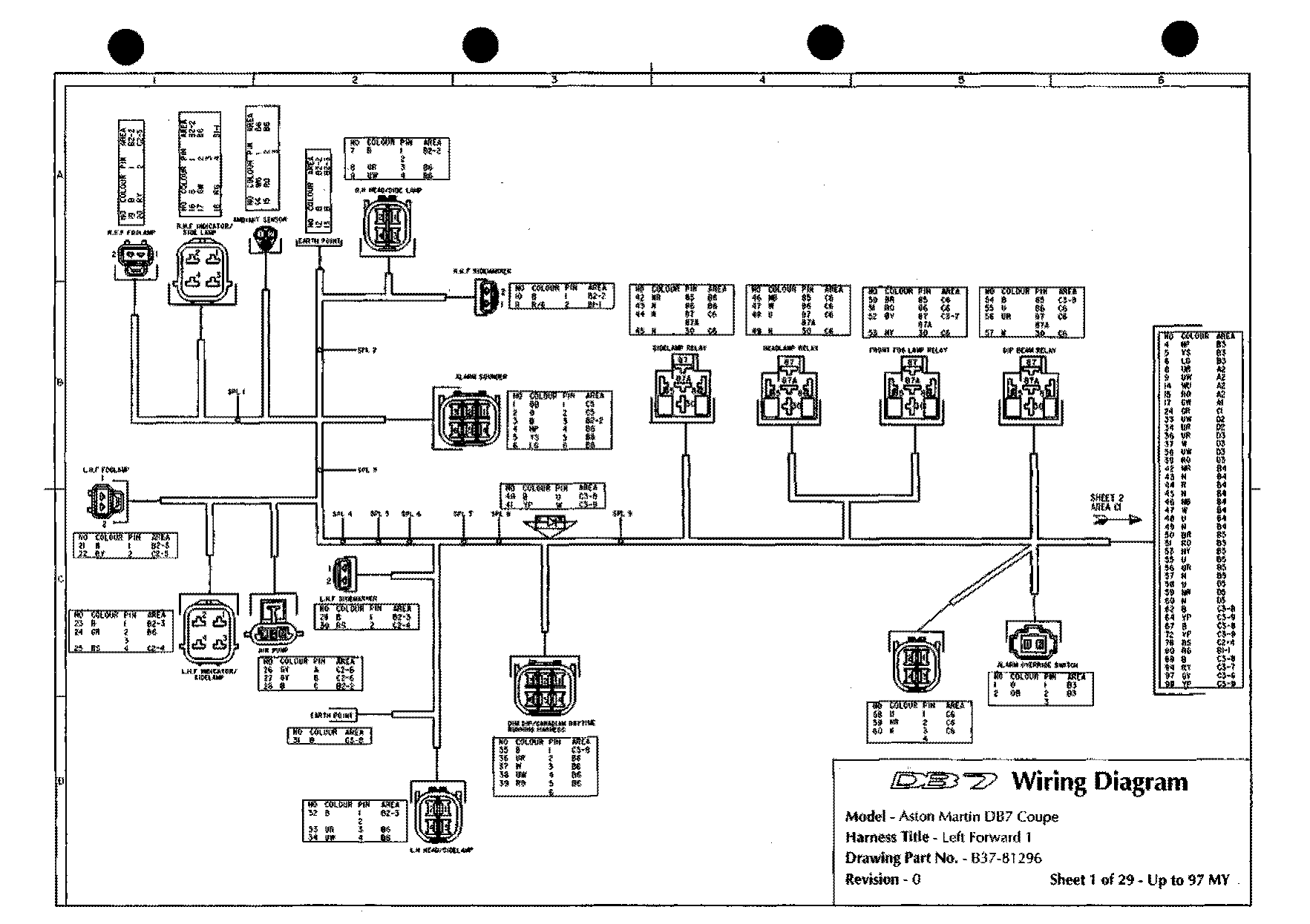
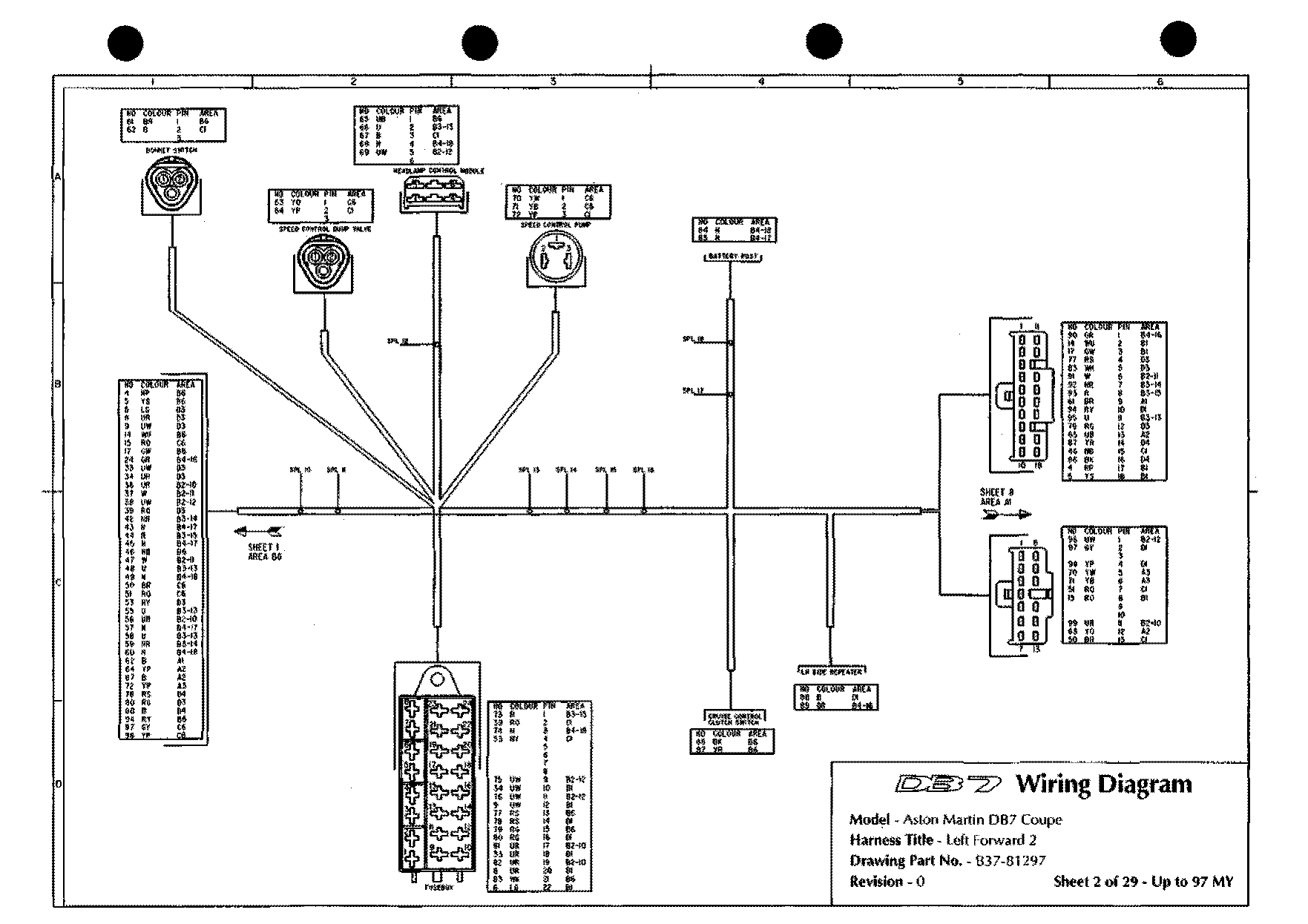
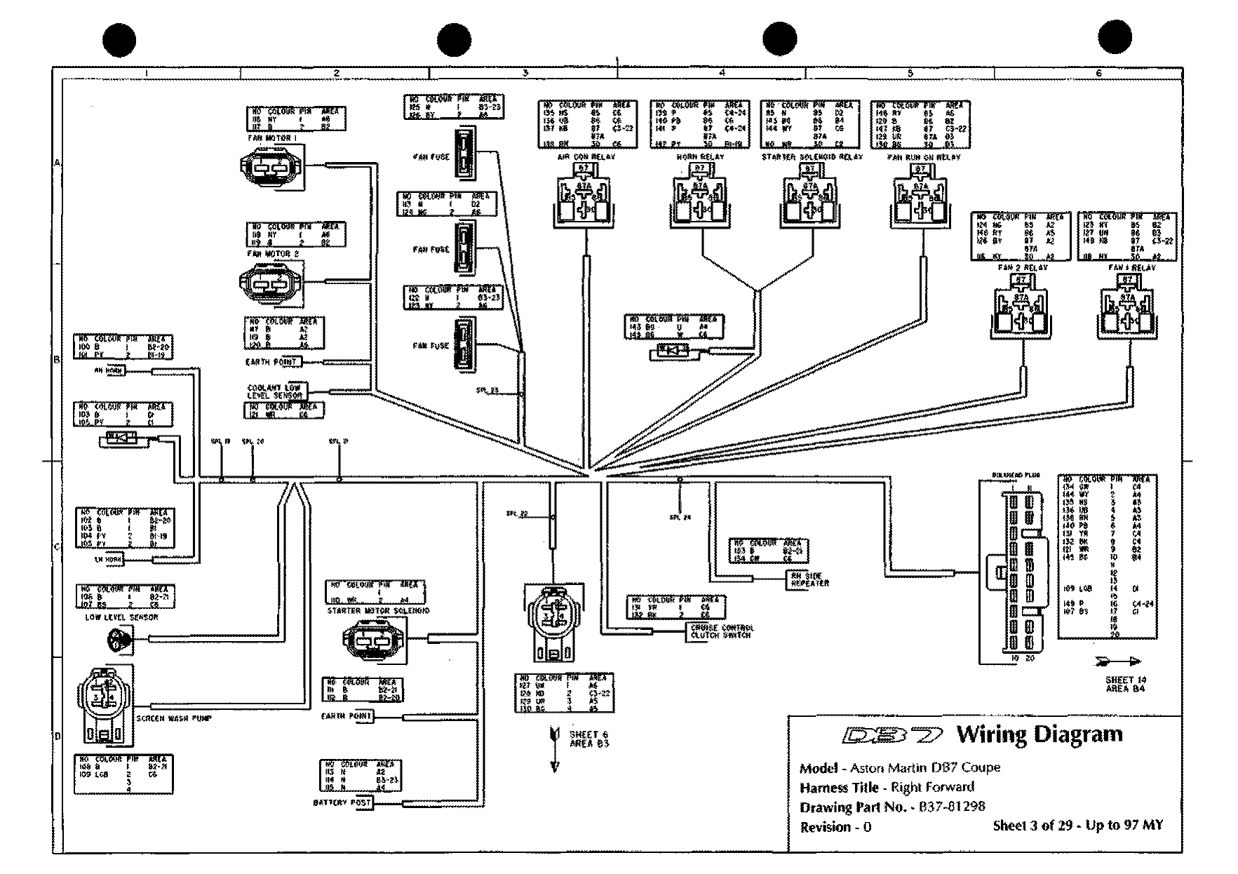
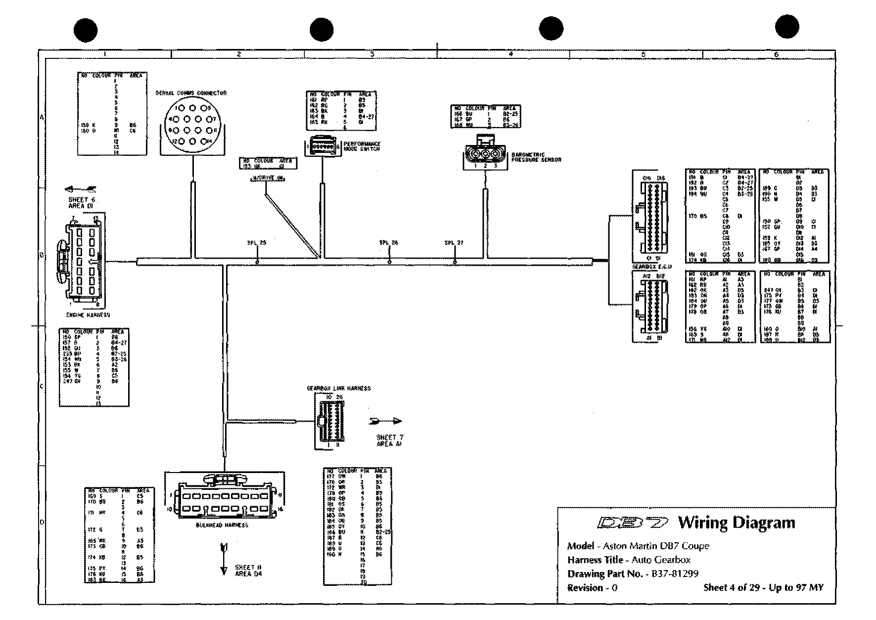
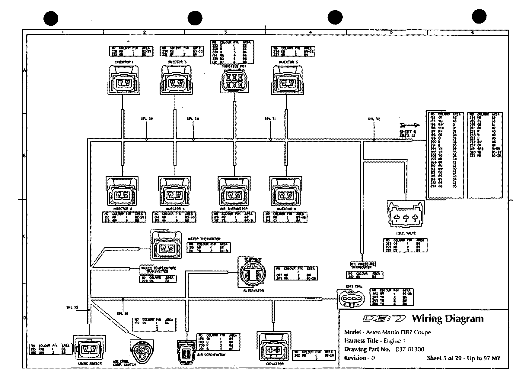
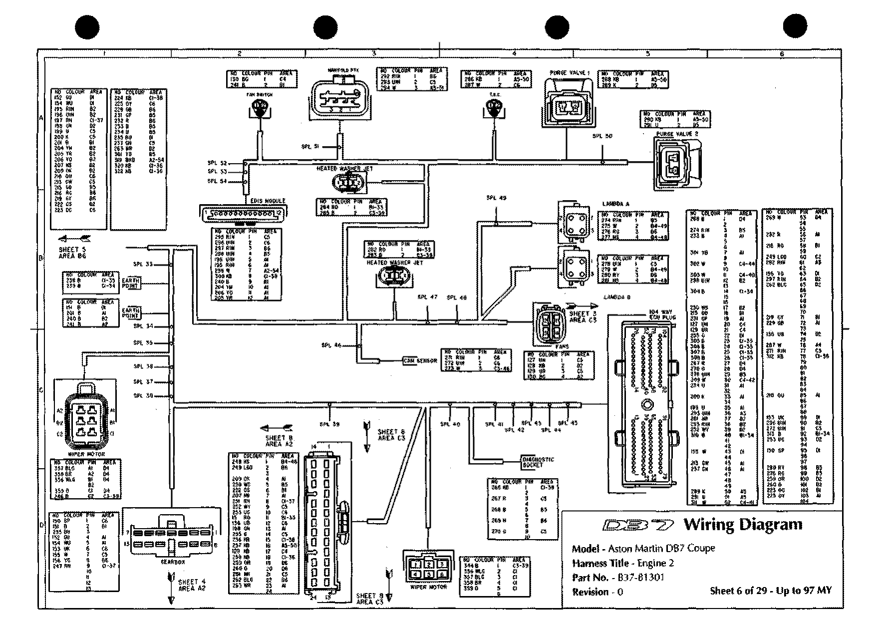
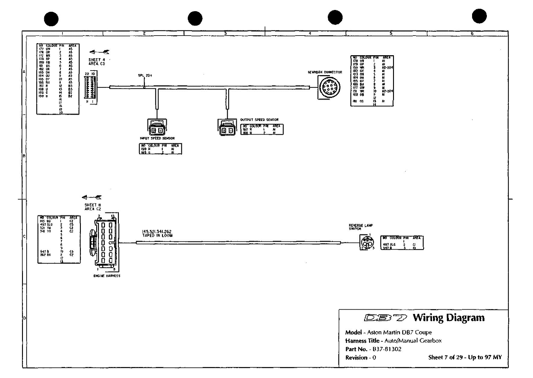
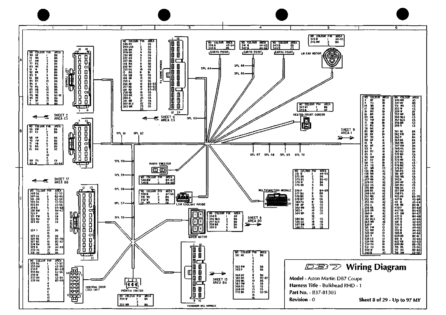
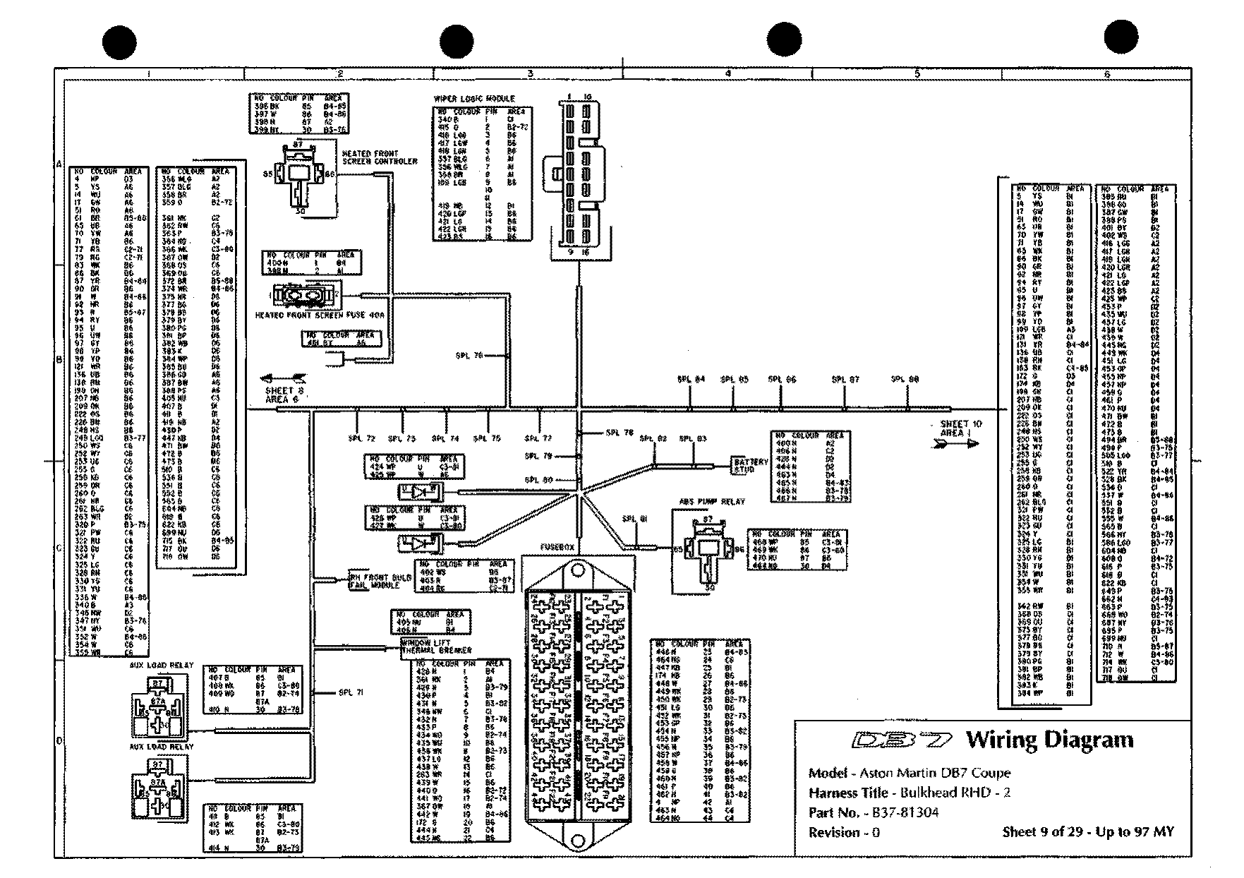
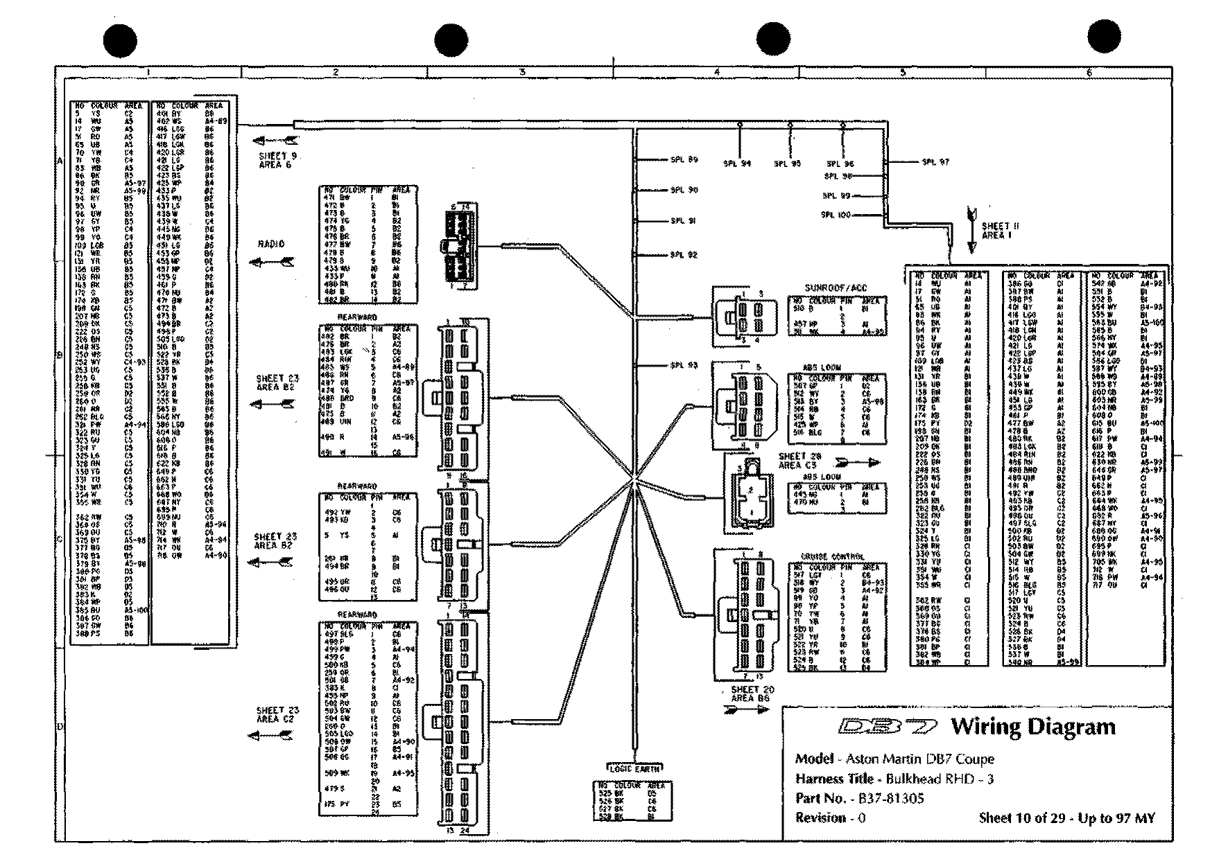
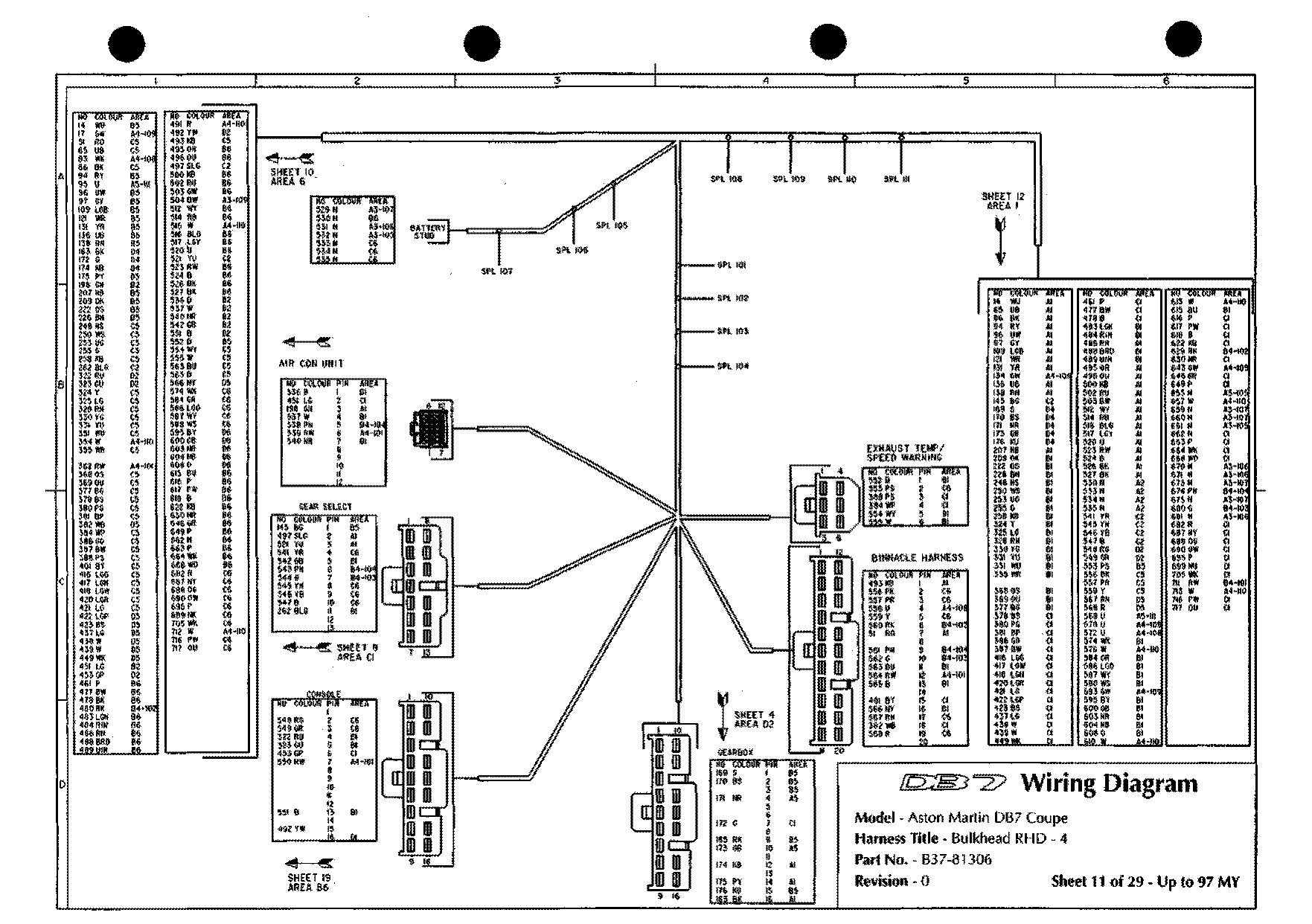
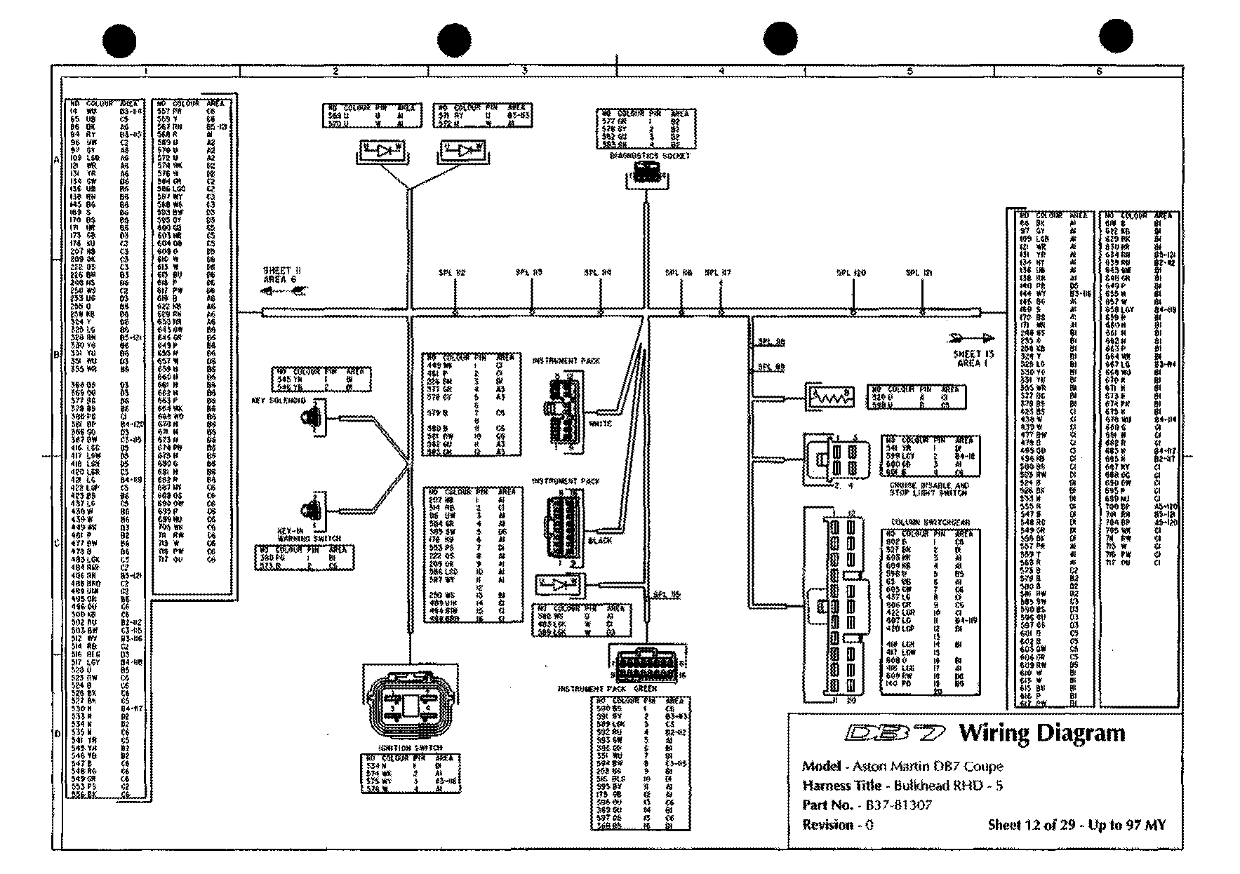
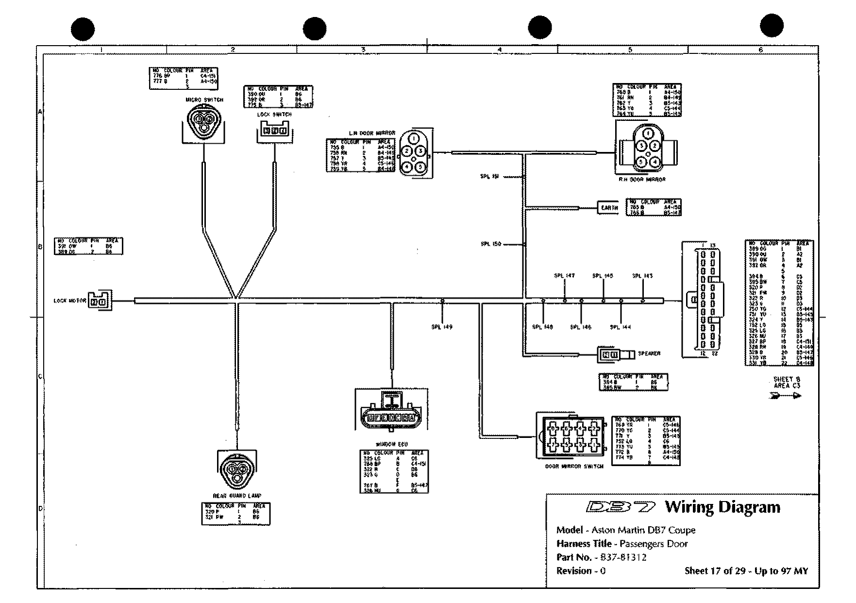
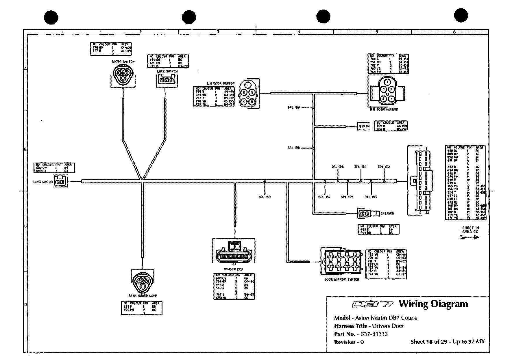
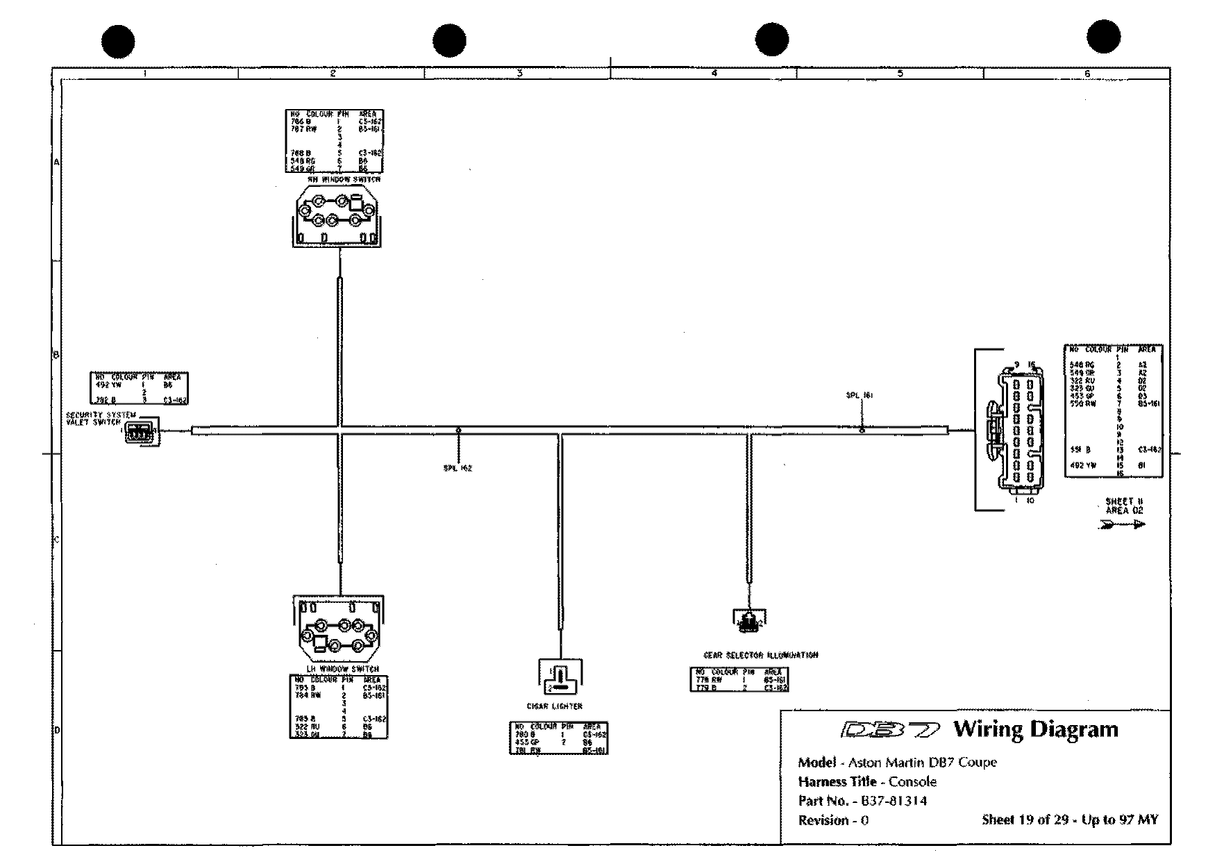
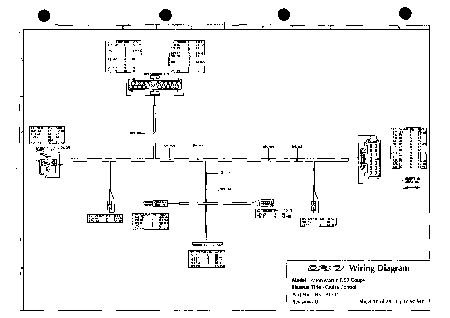
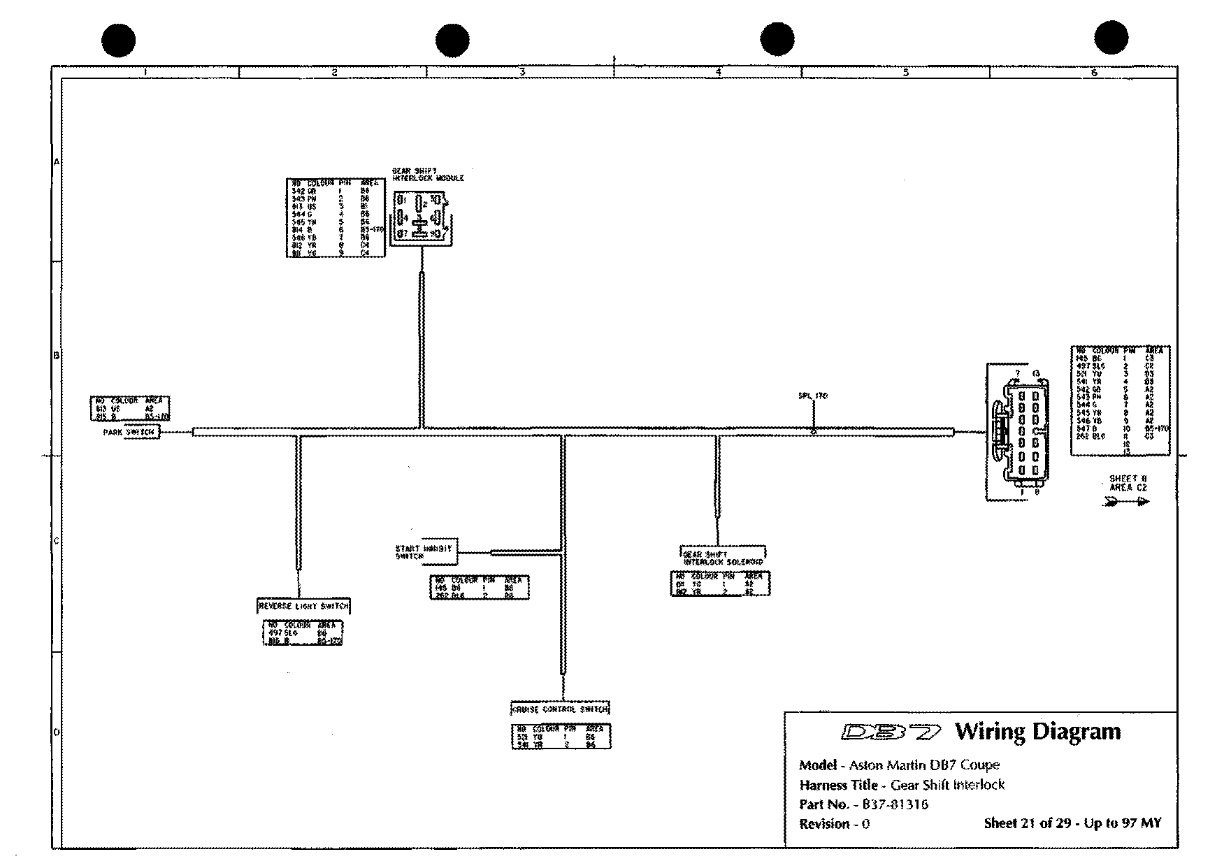
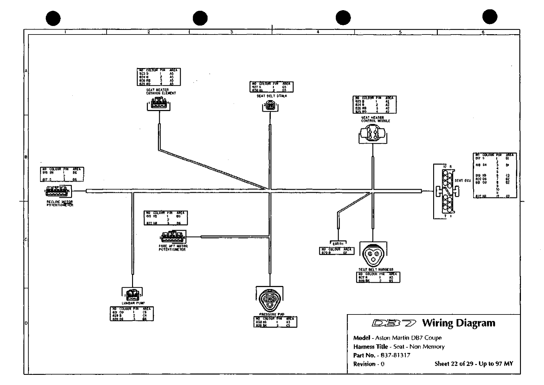
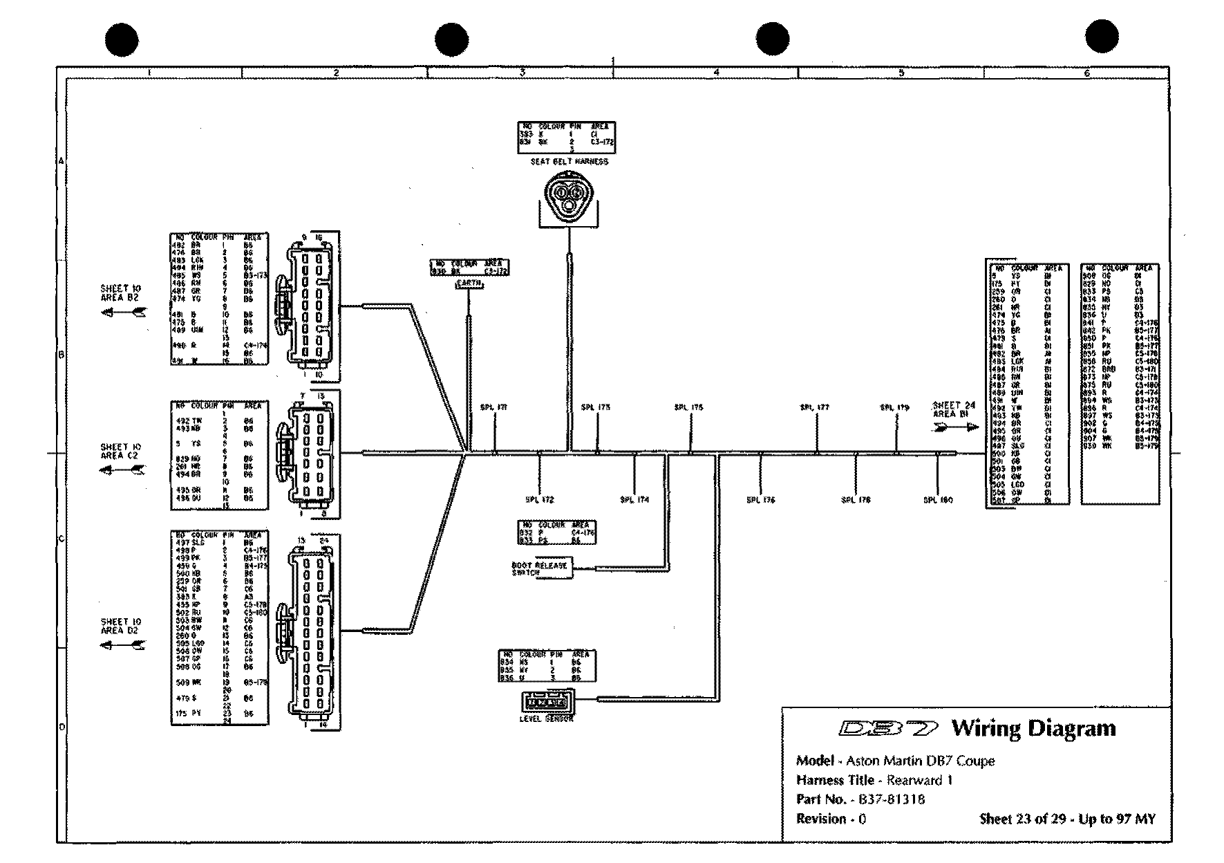
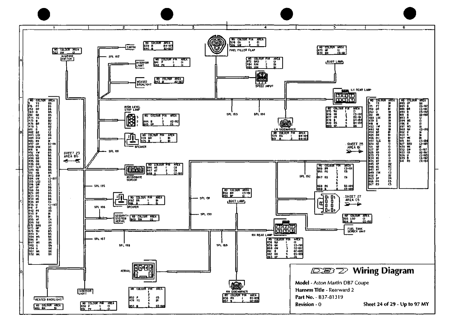
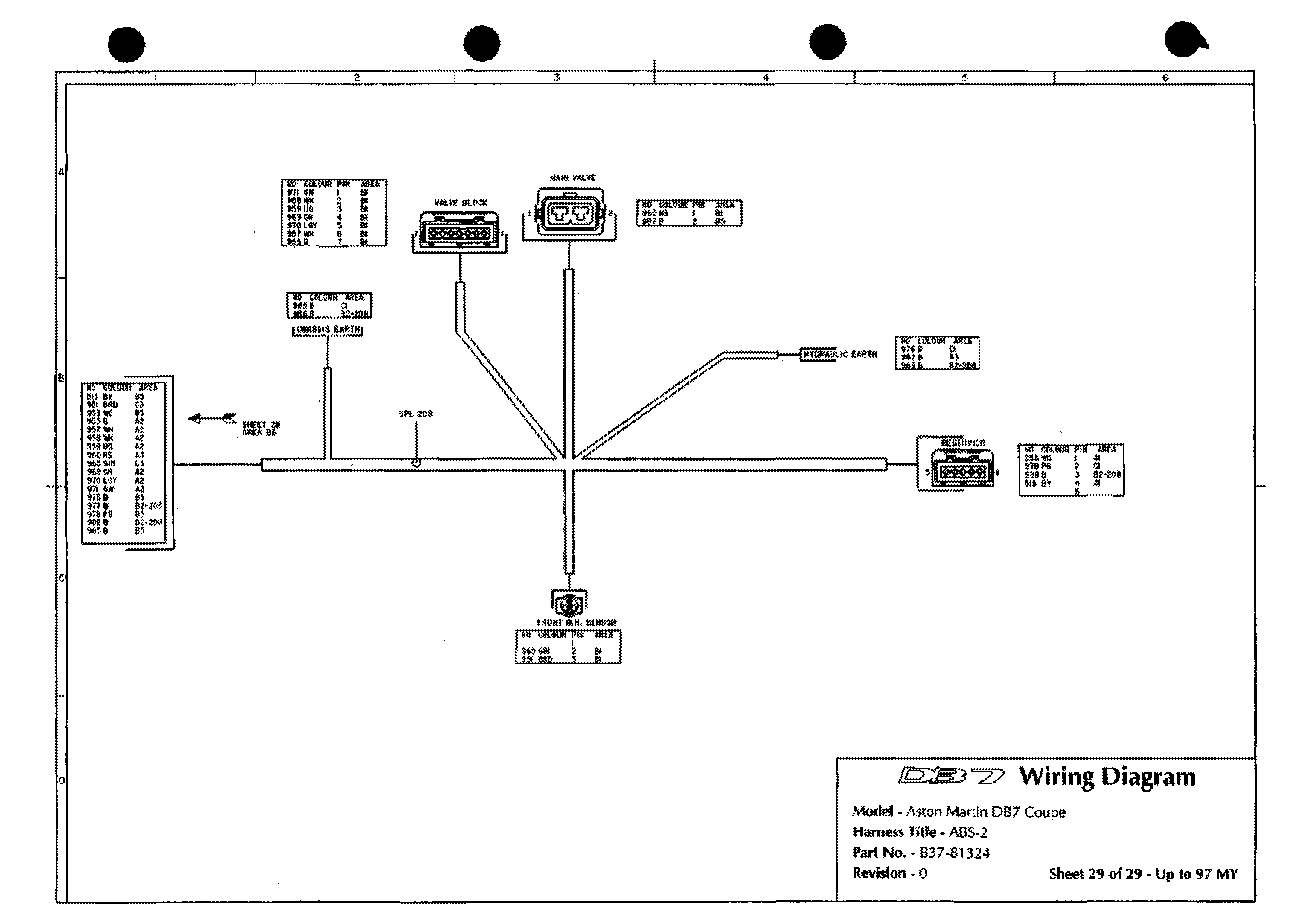
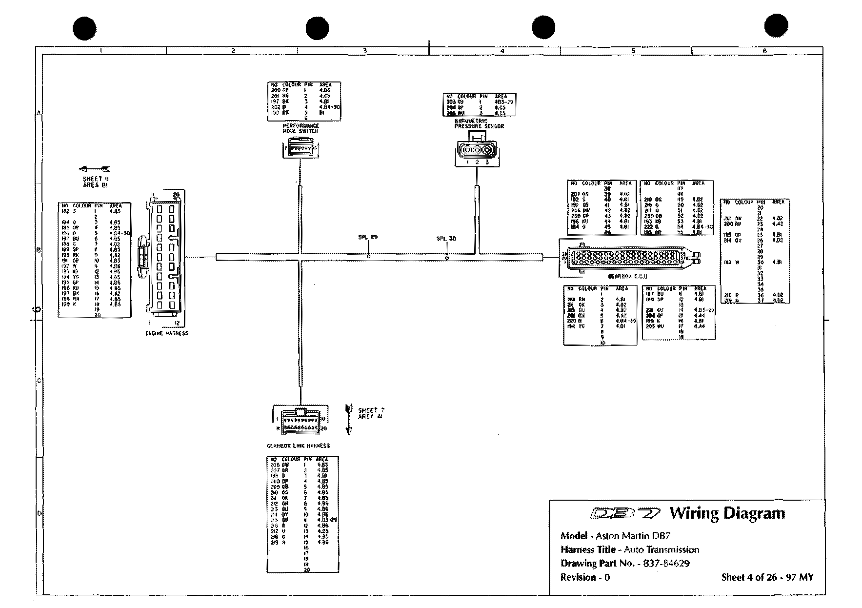
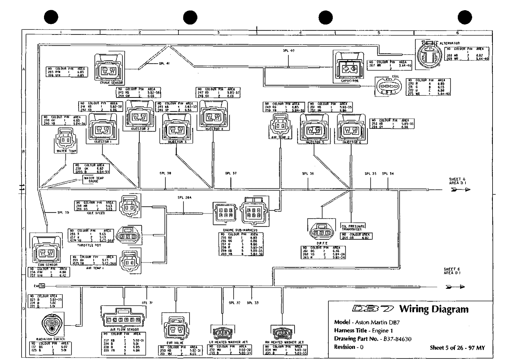
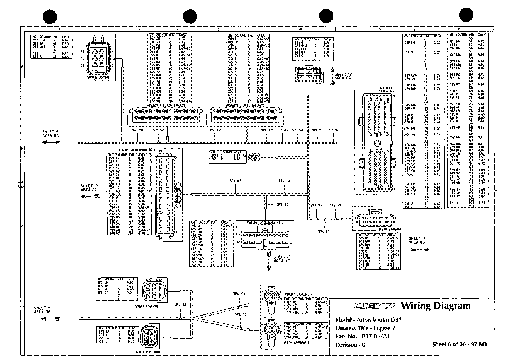
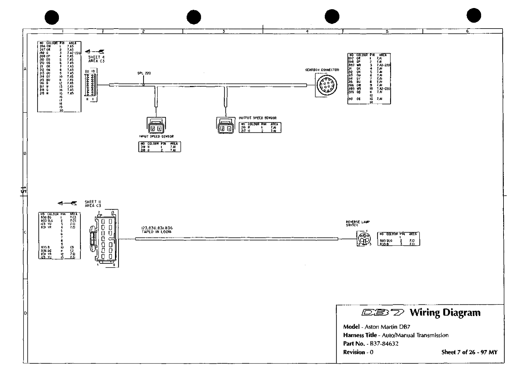
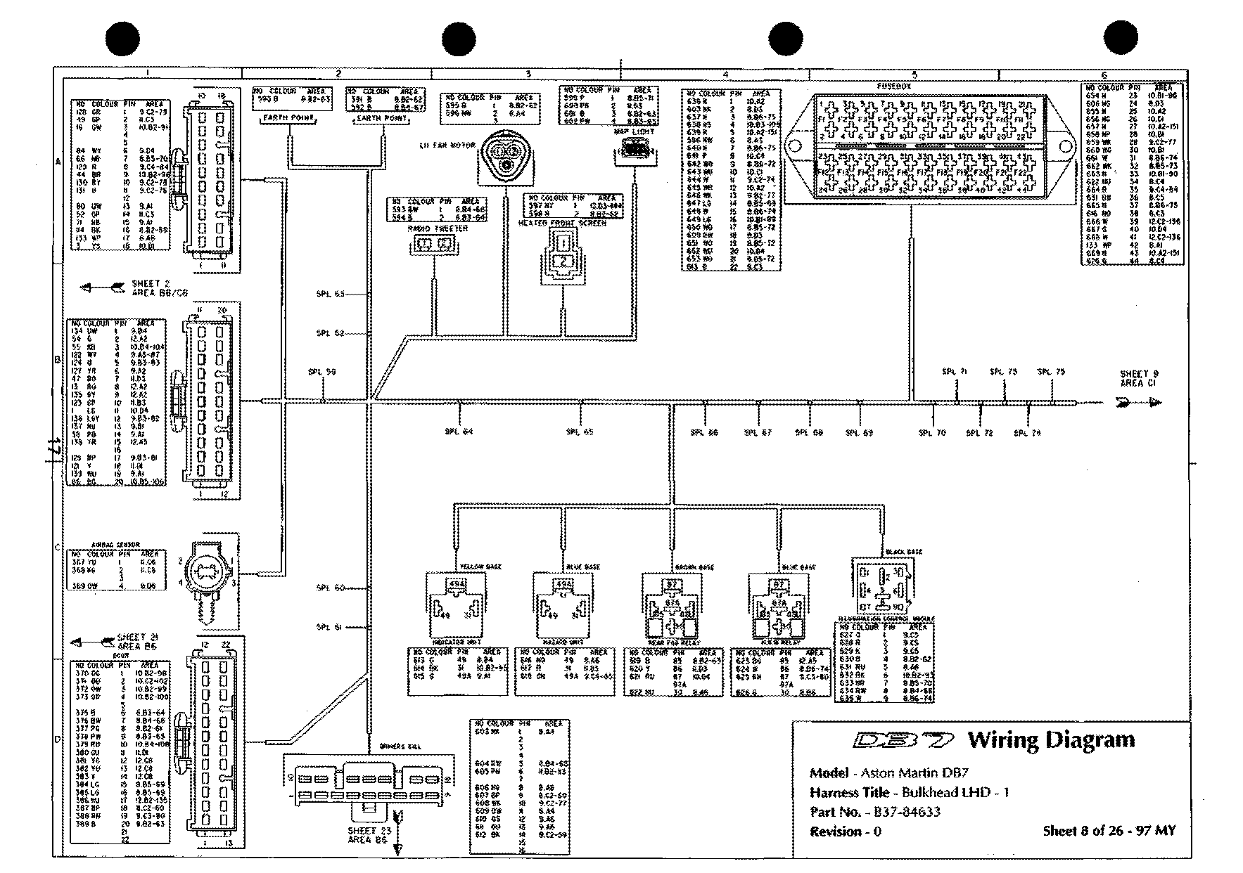
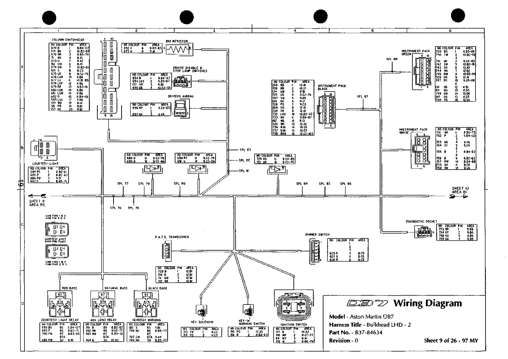
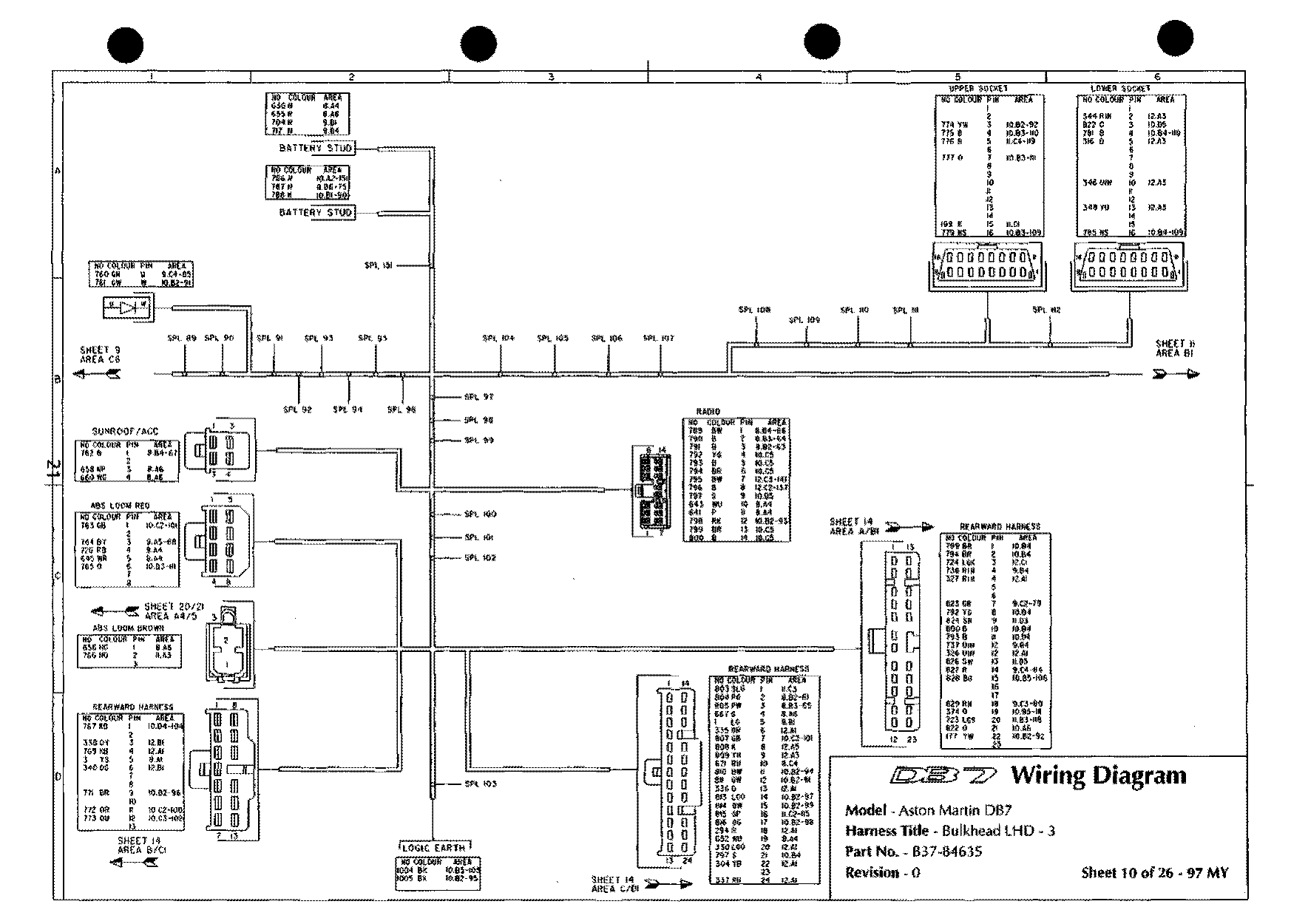
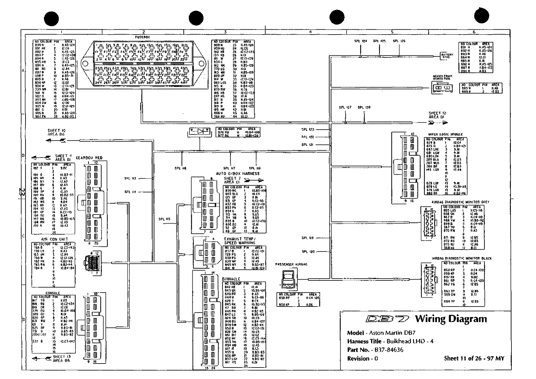
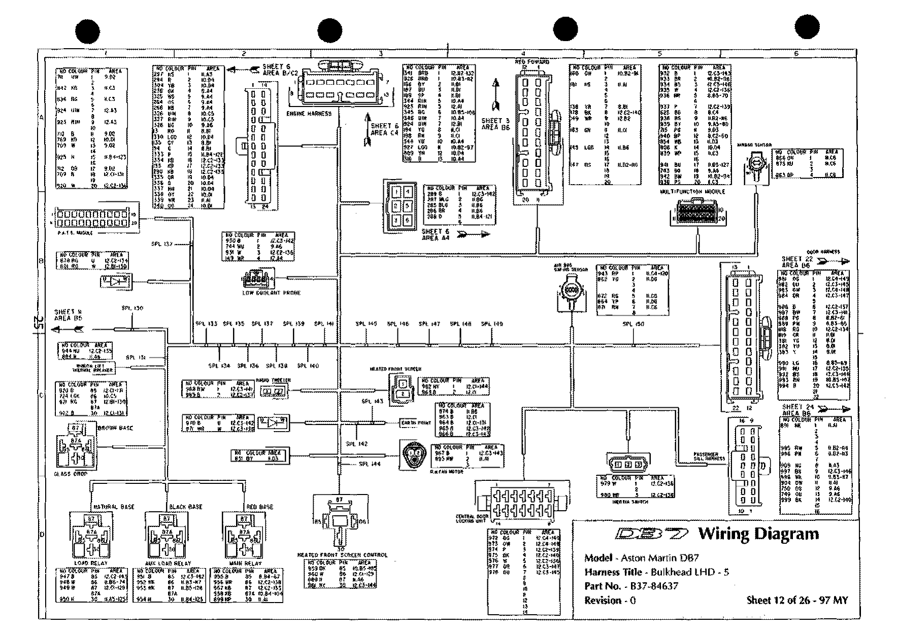
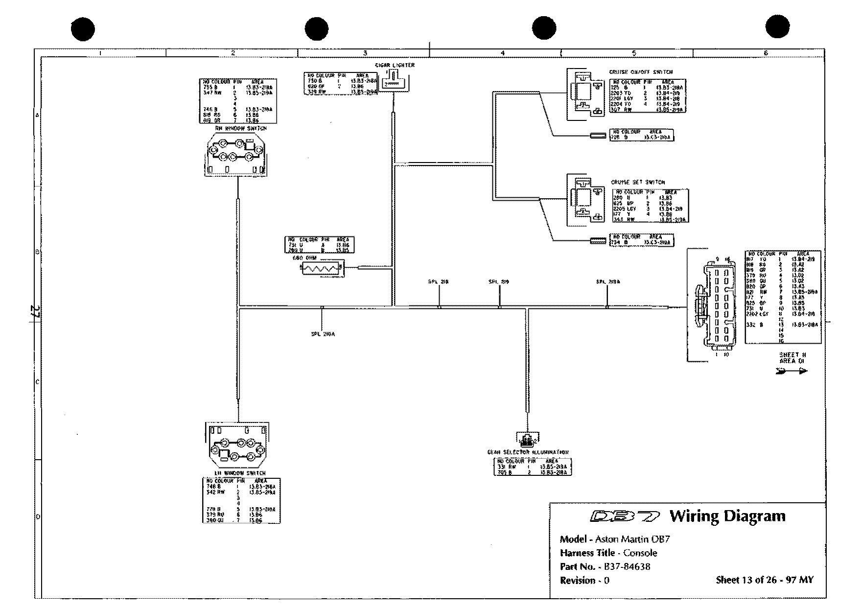
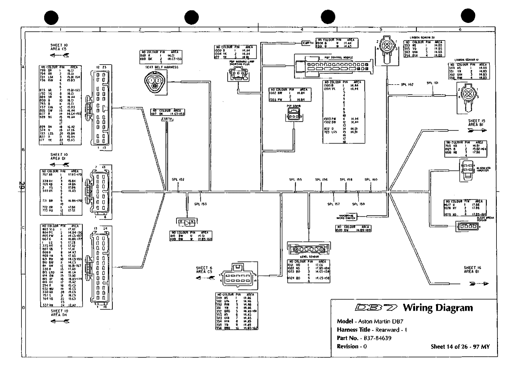
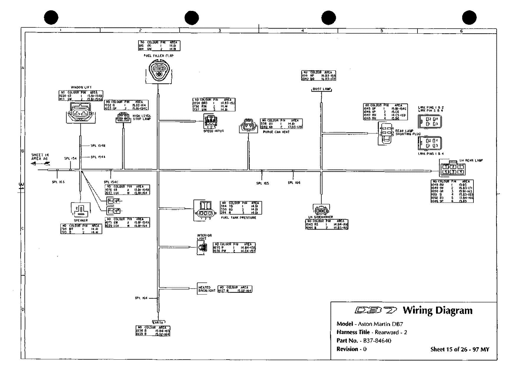
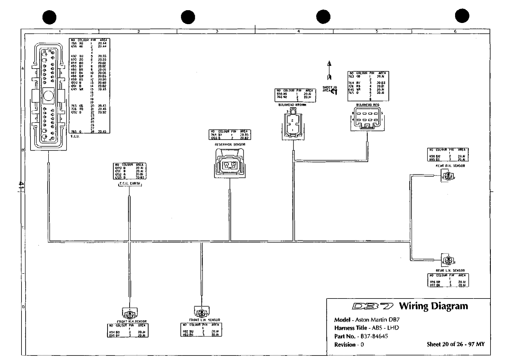
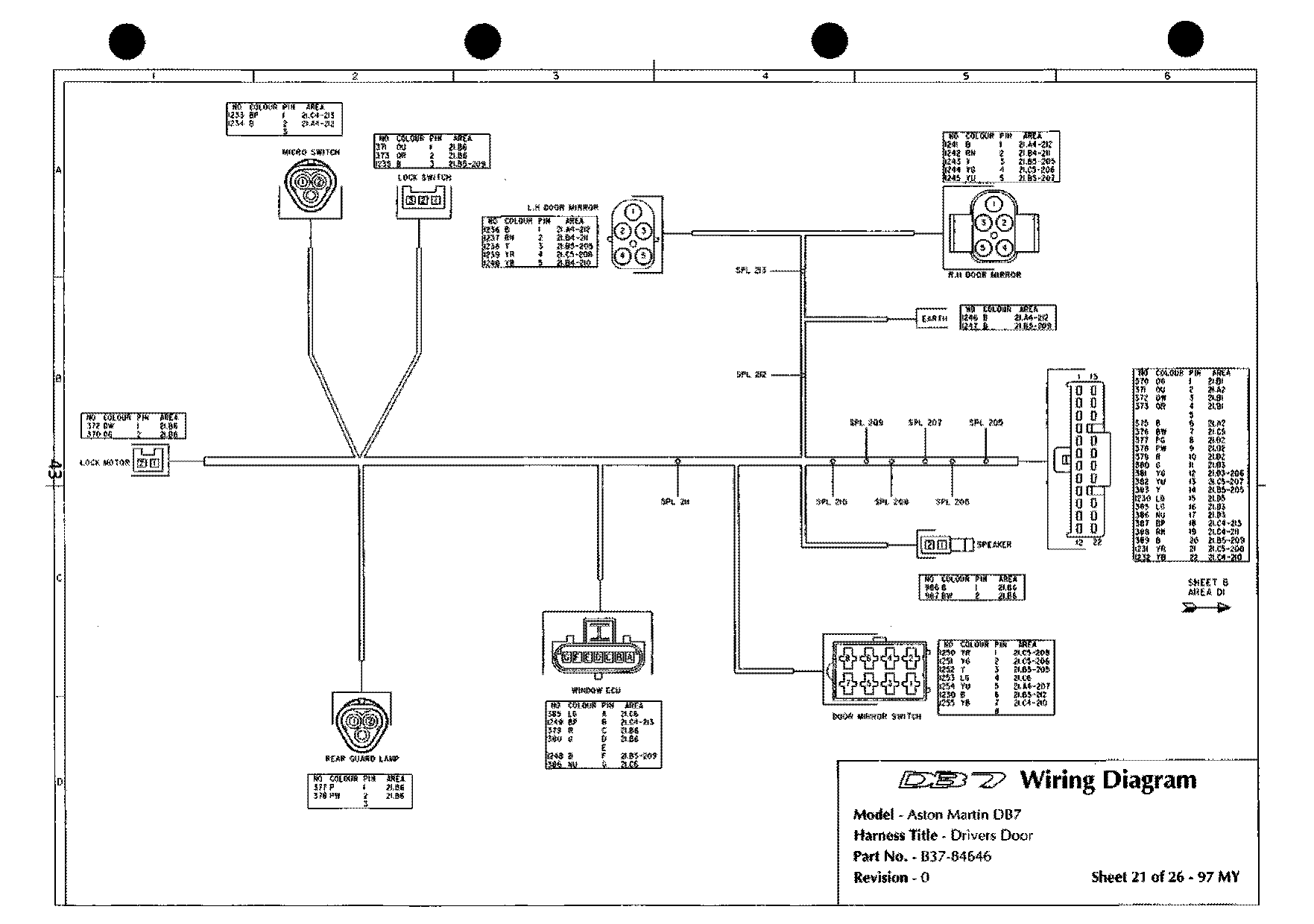
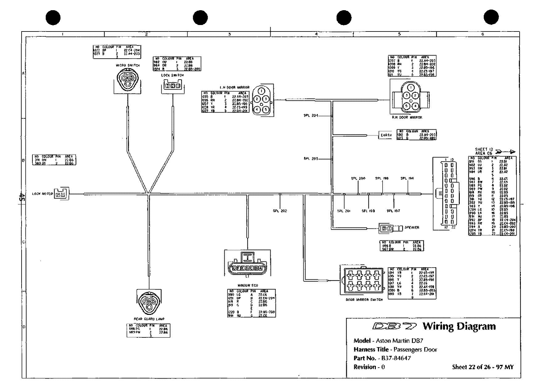
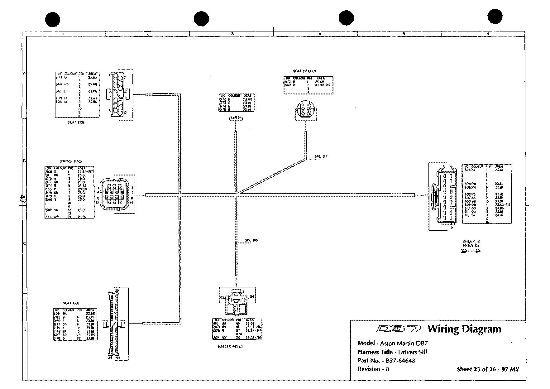
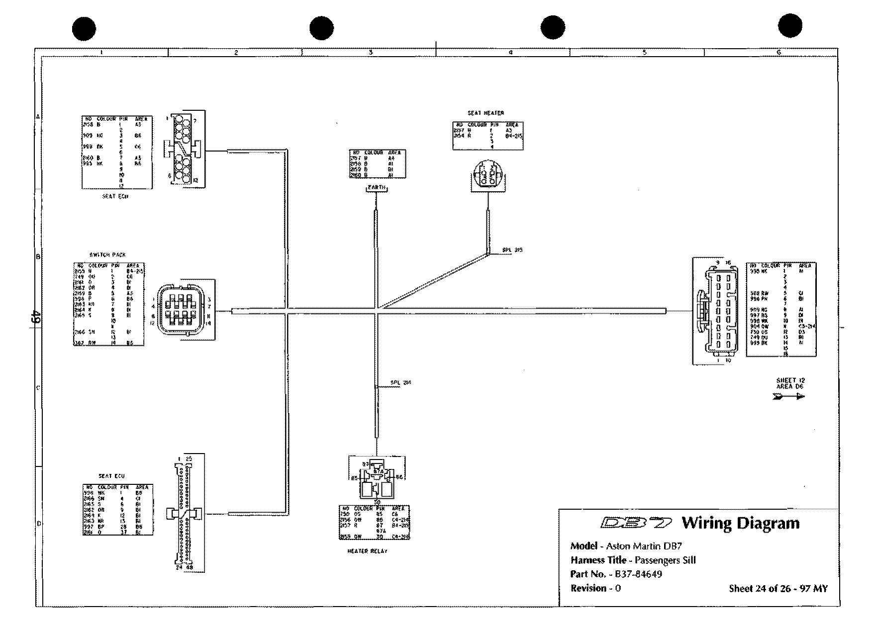
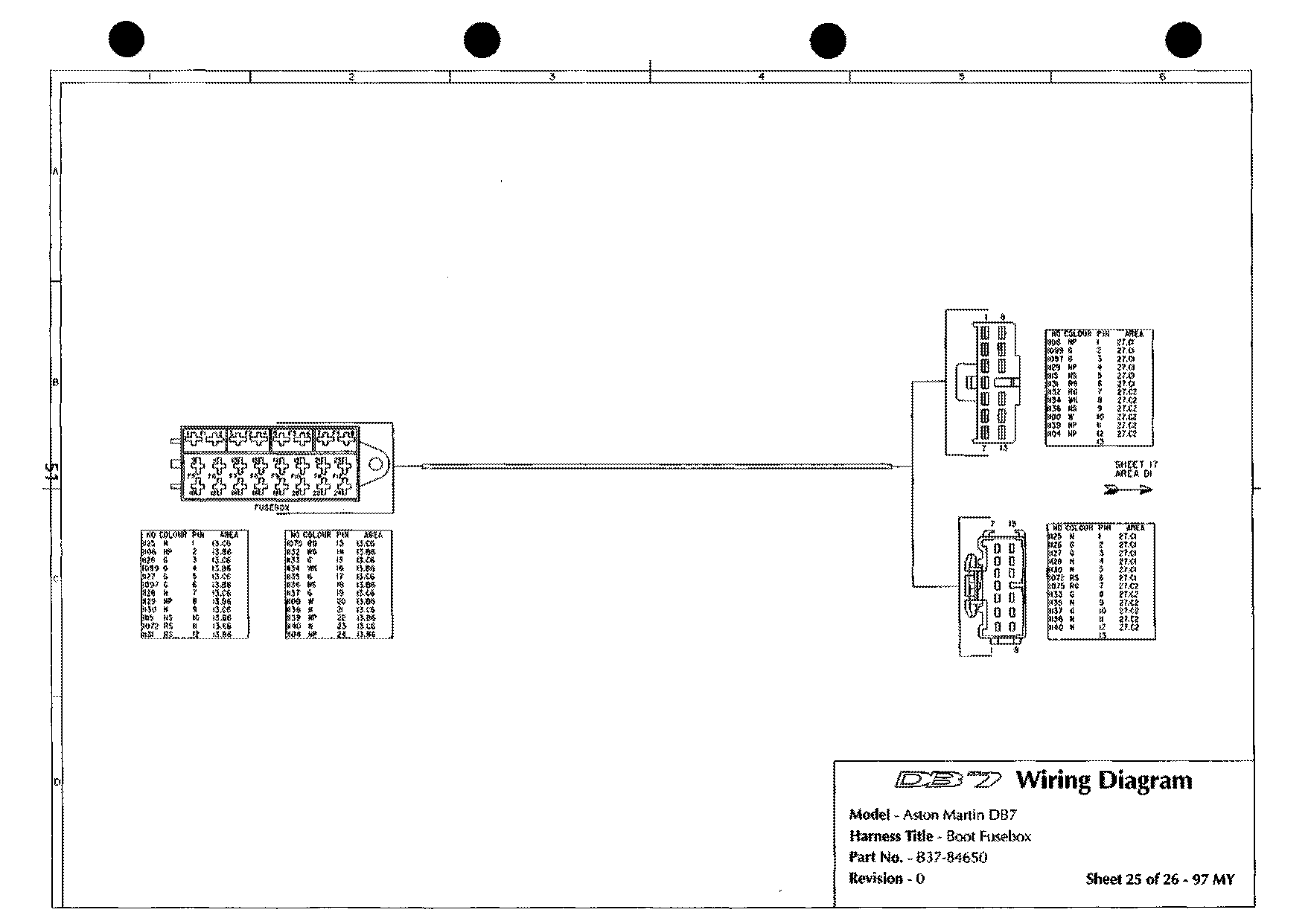
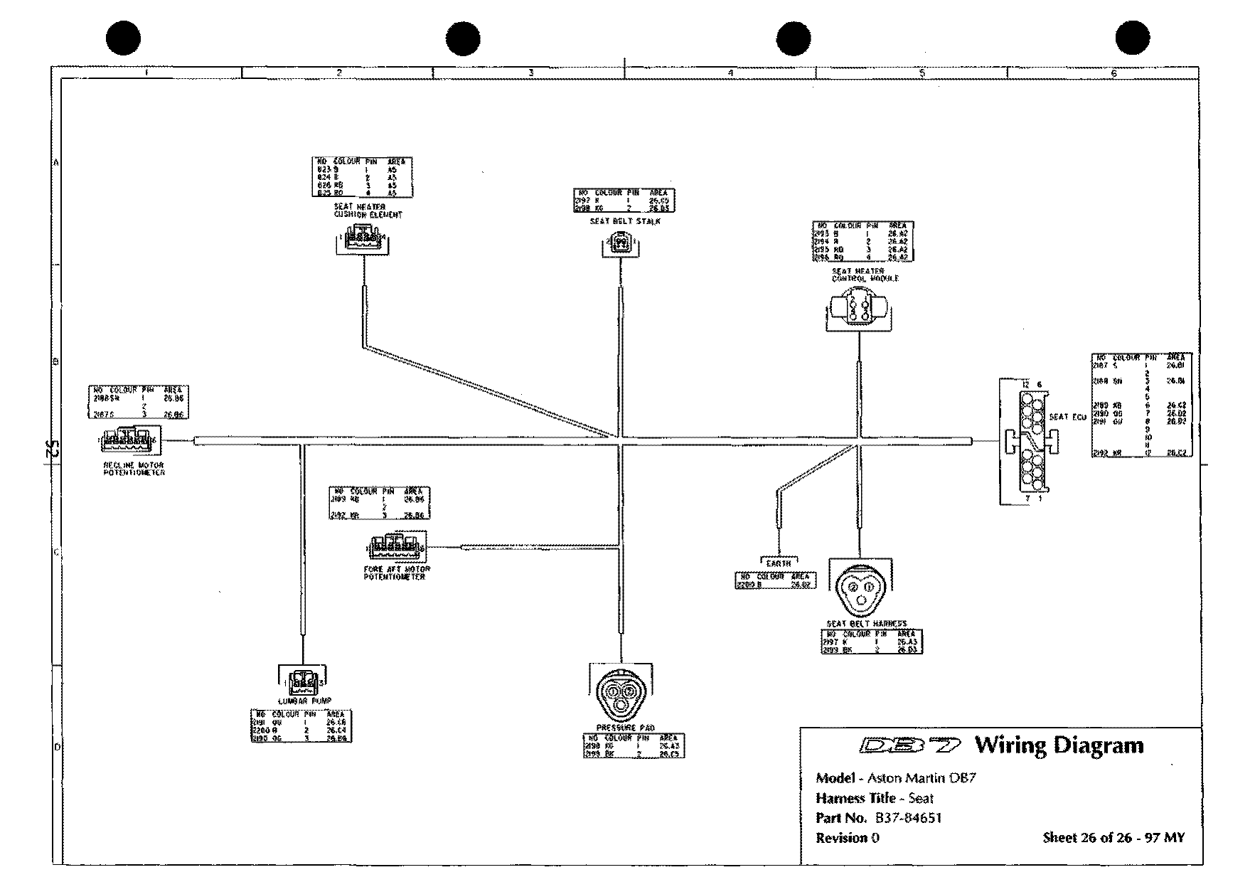
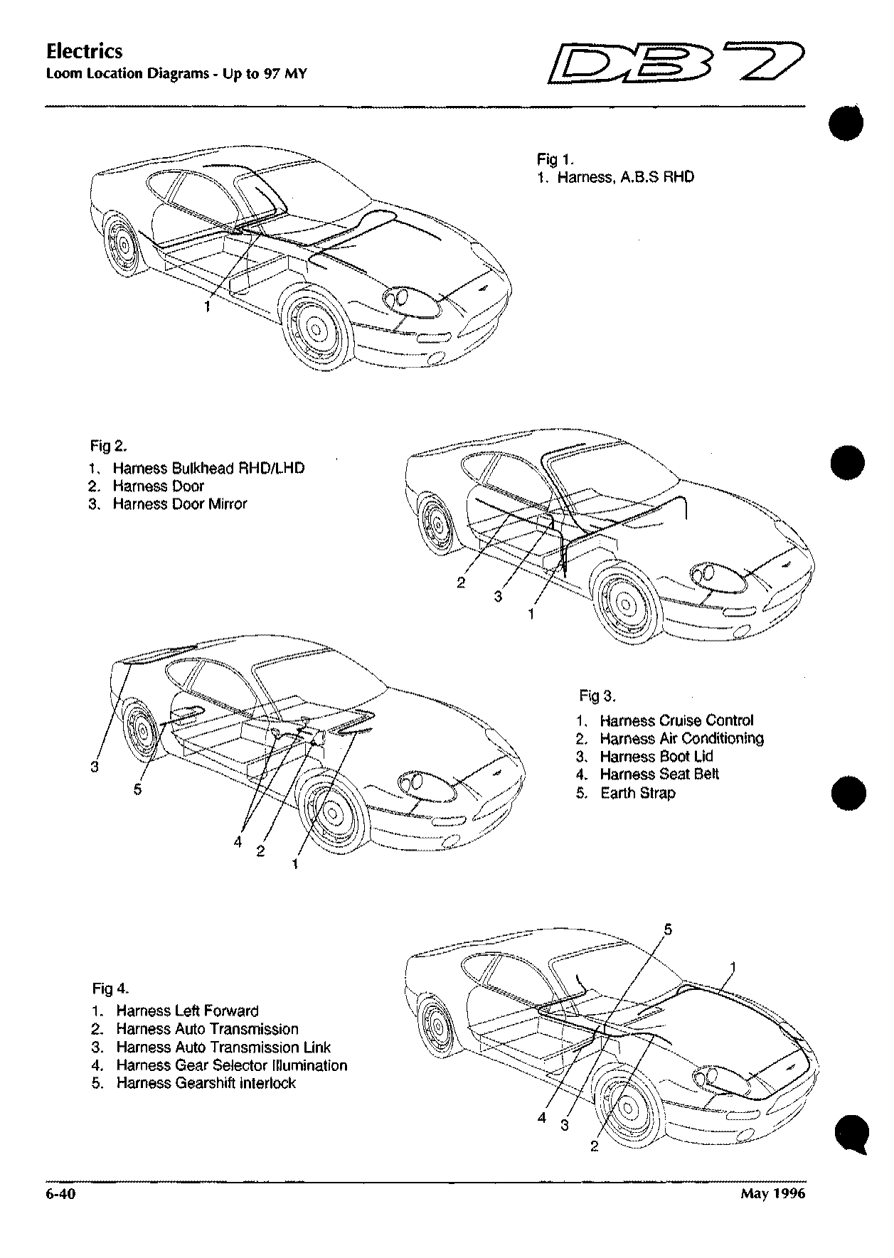
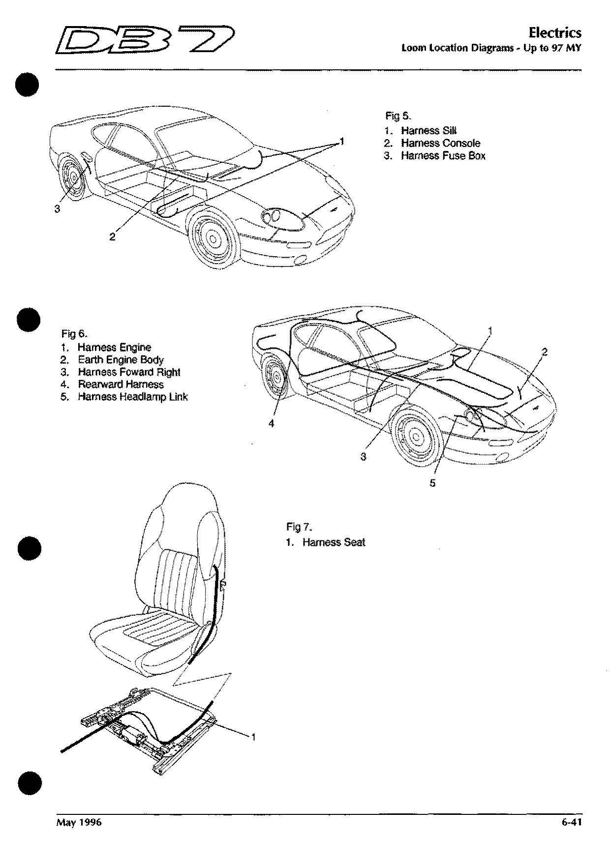
Up to 97 MY: 29 harness sheets drawn for the right-hand-drive coupe. Each shows the connectors on one harness with wire numbers, colours and pins; the “sheet N area XX” arrows show where a wire continues. Splice lists give every wire joined at each splice (SPL).
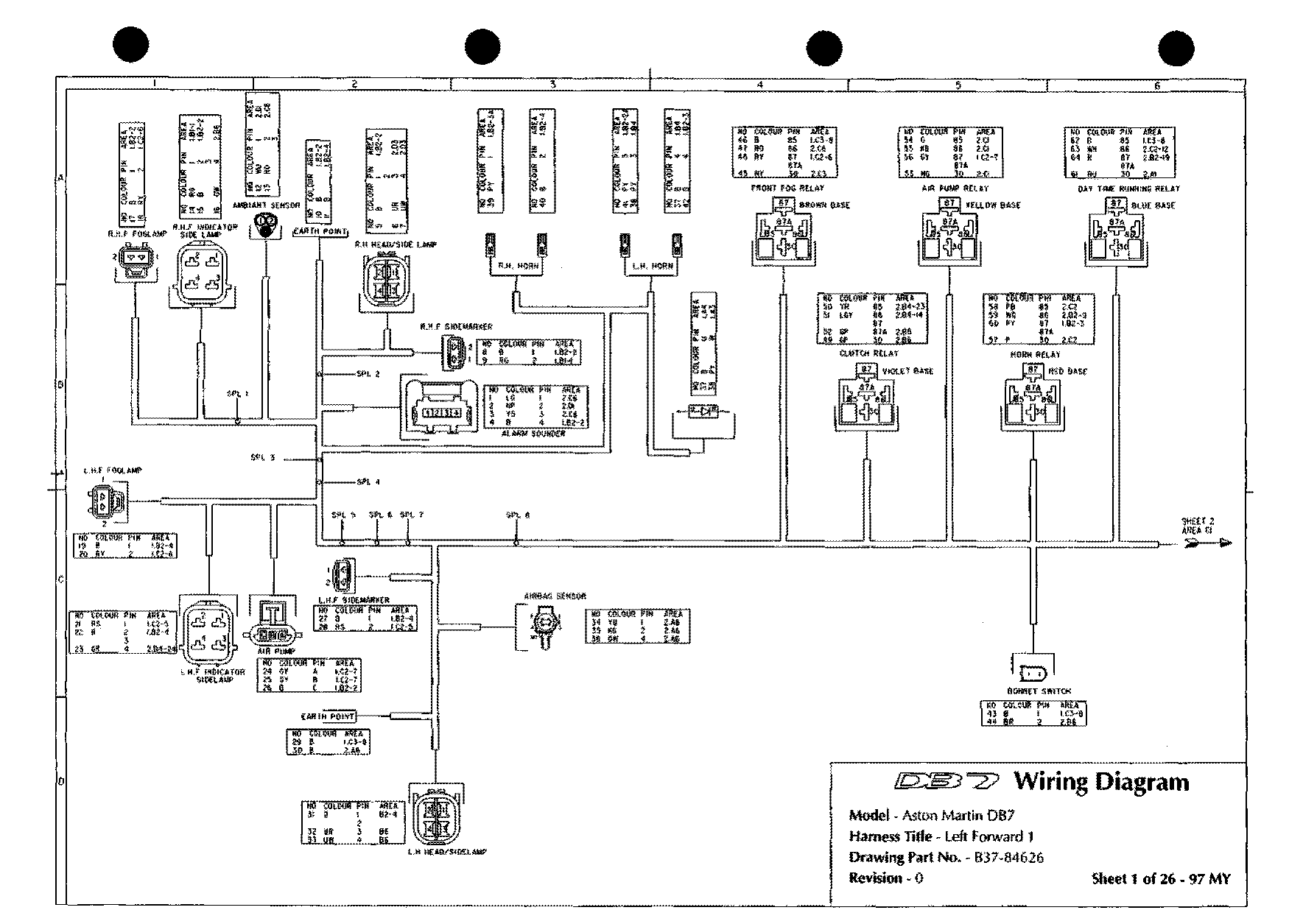
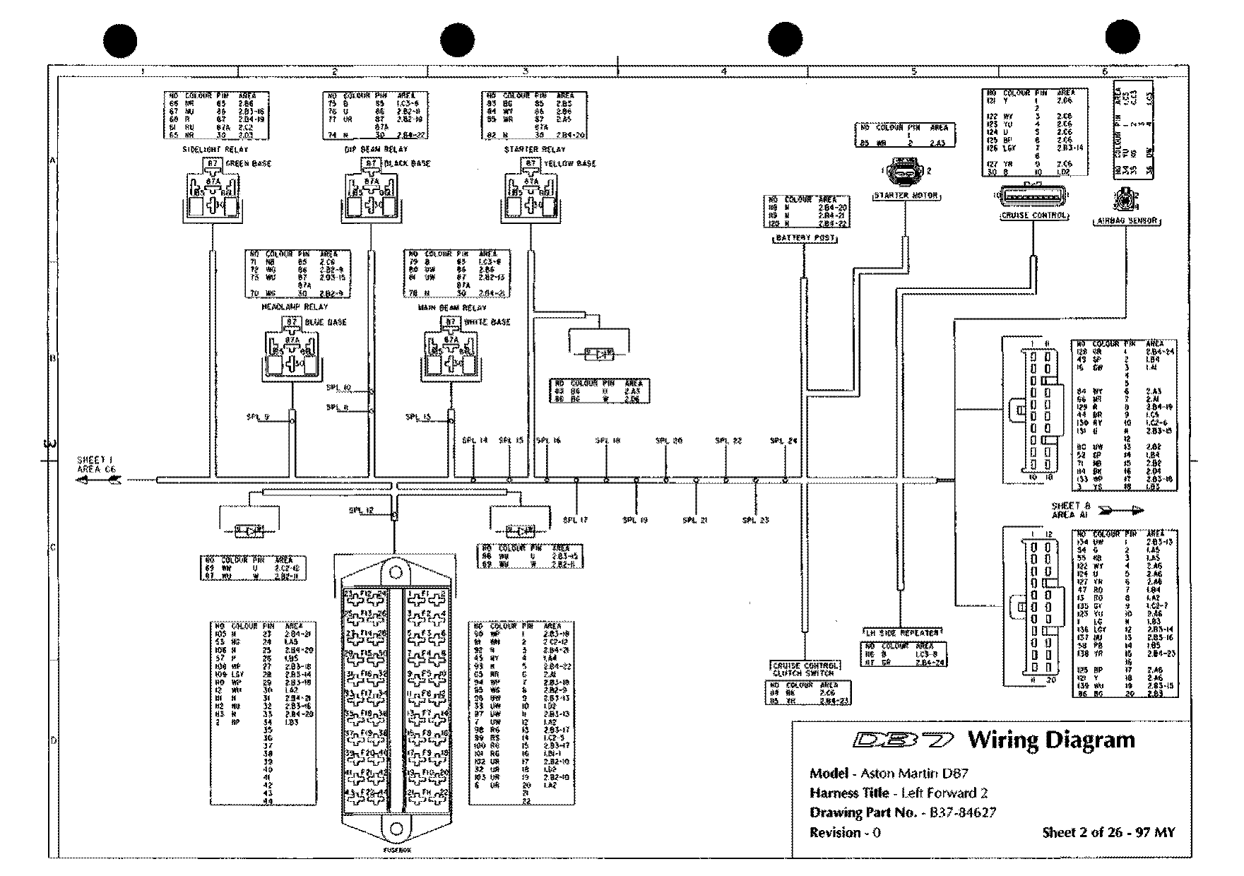
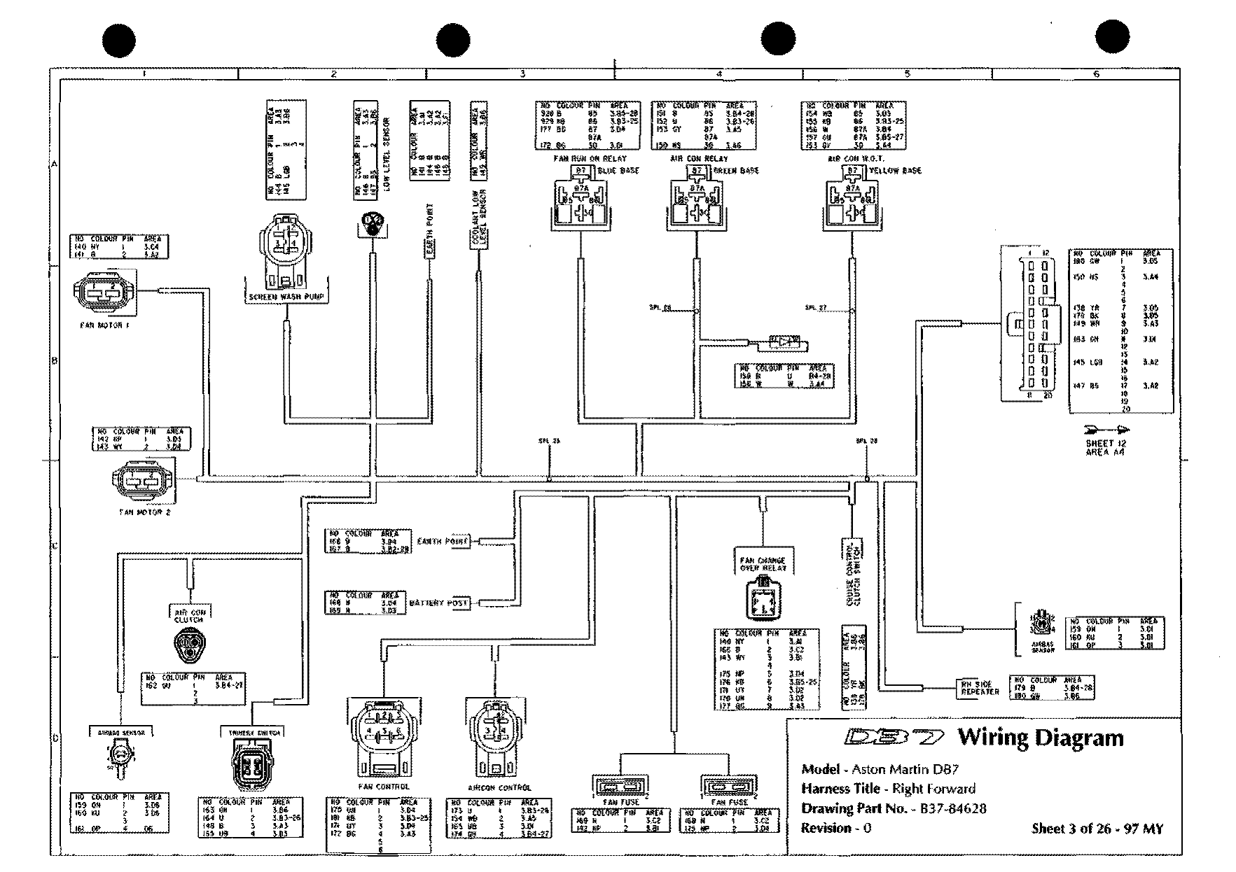
97 MY on: 26 harness sheets. The bulkhead and ABS harness sheets in this set are drawn for left-hand drive; right-hand-drive cars use the same circuits mirrored.
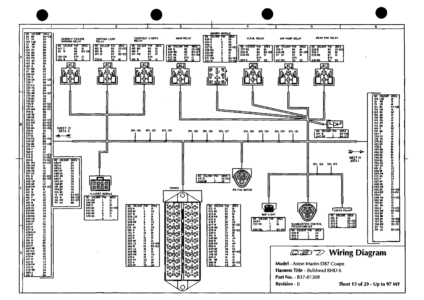
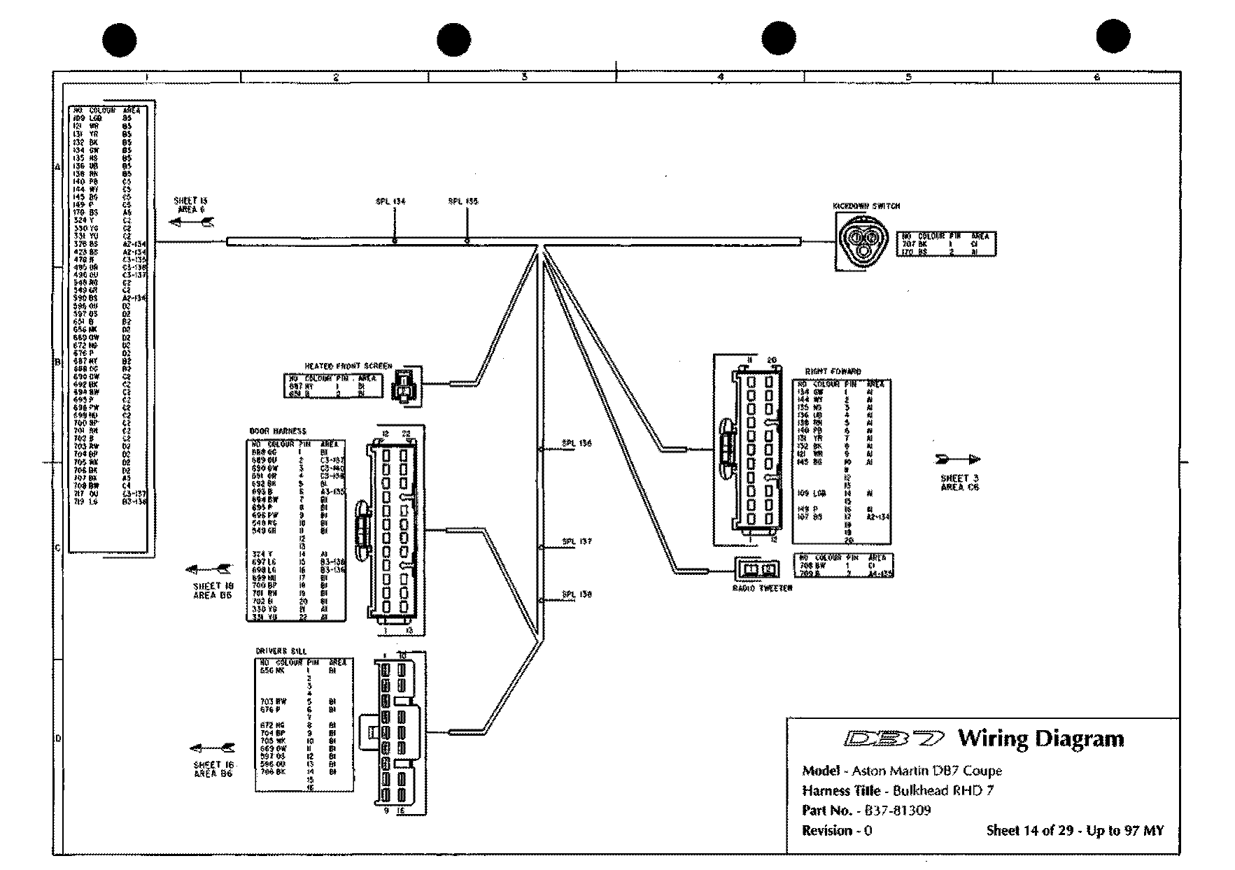
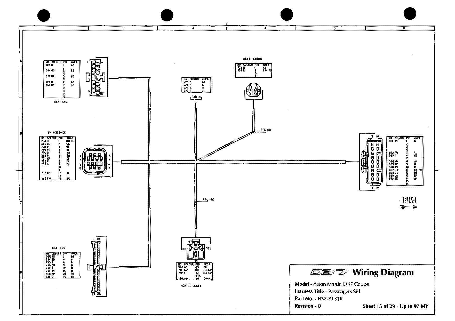
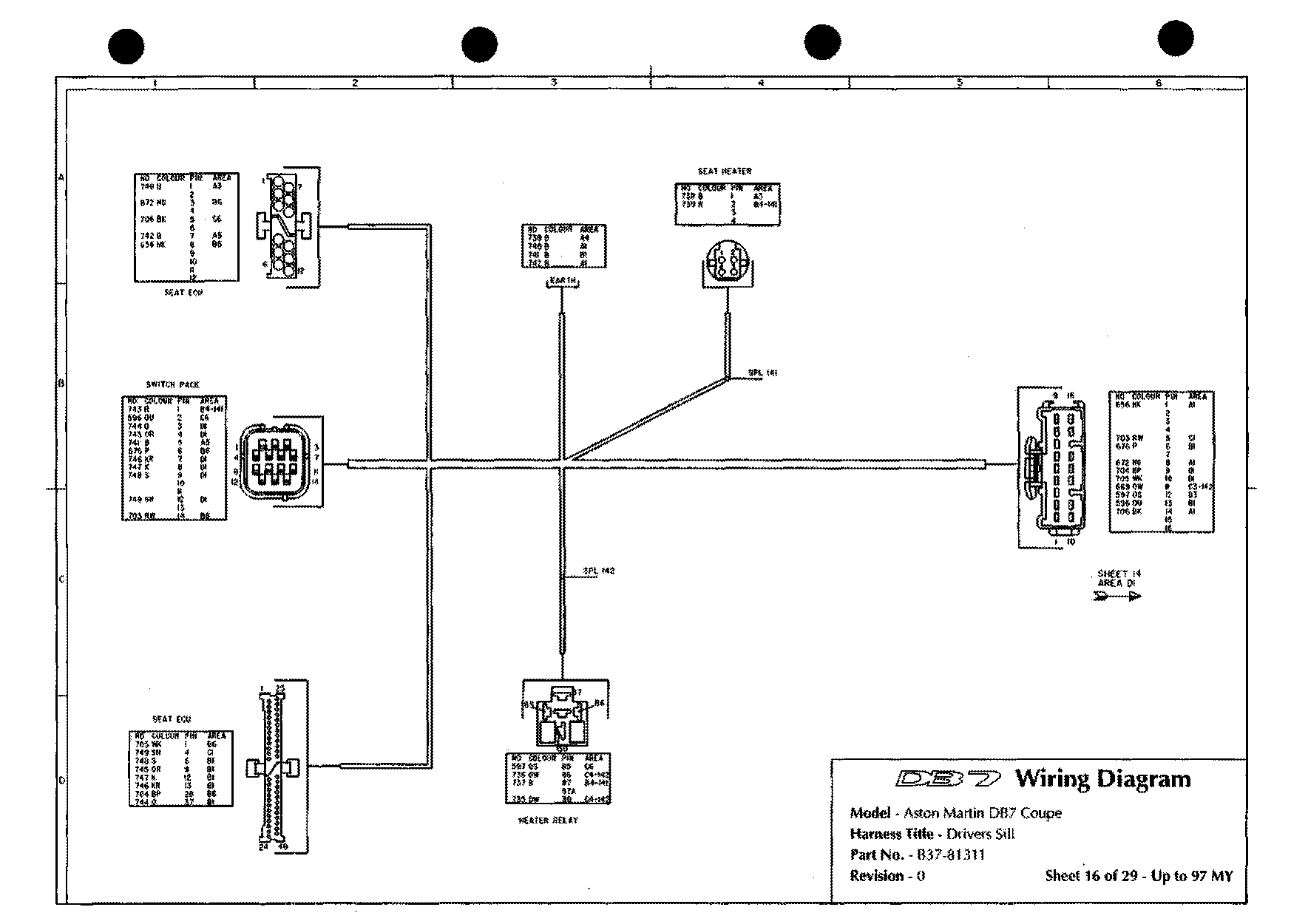
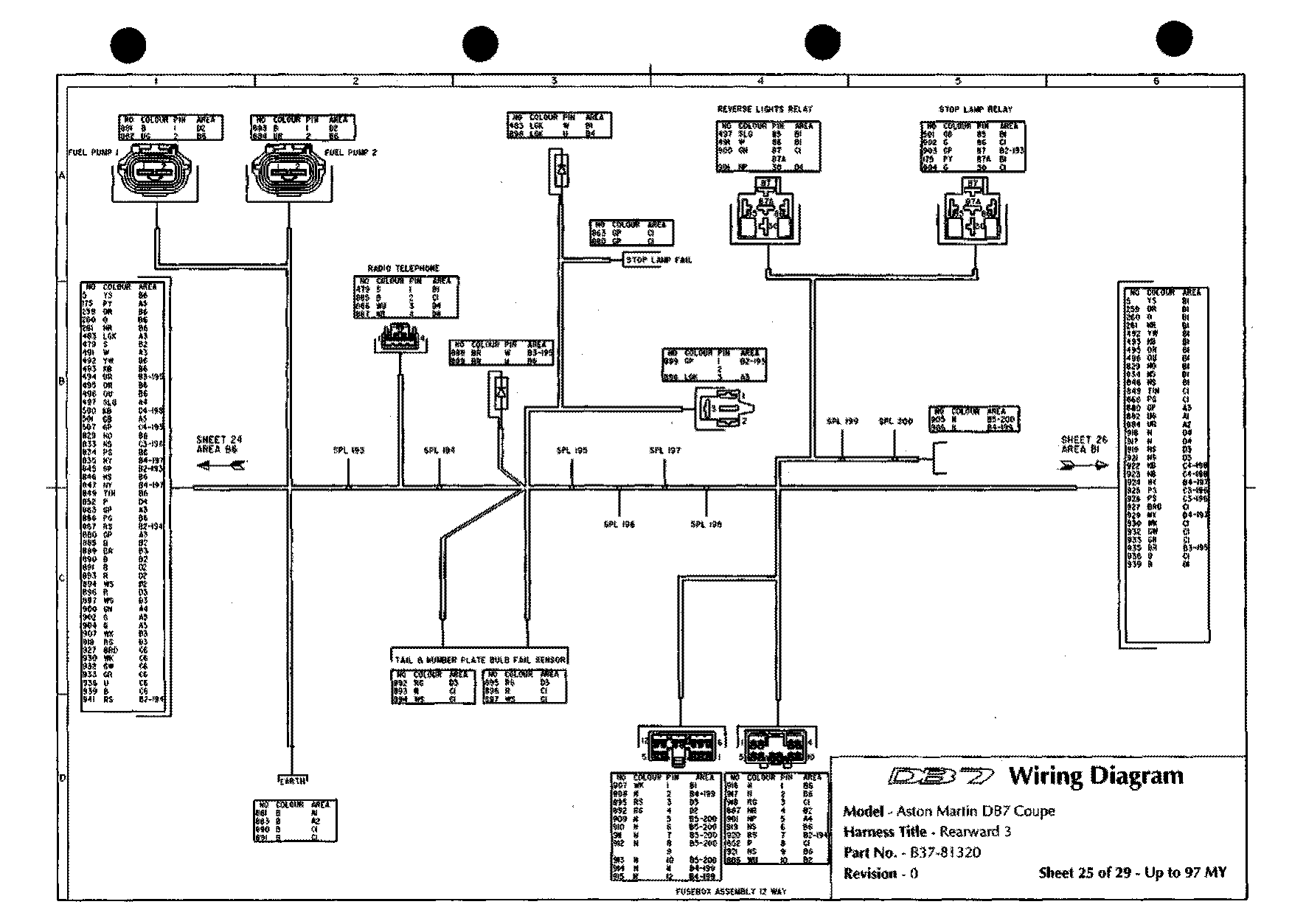
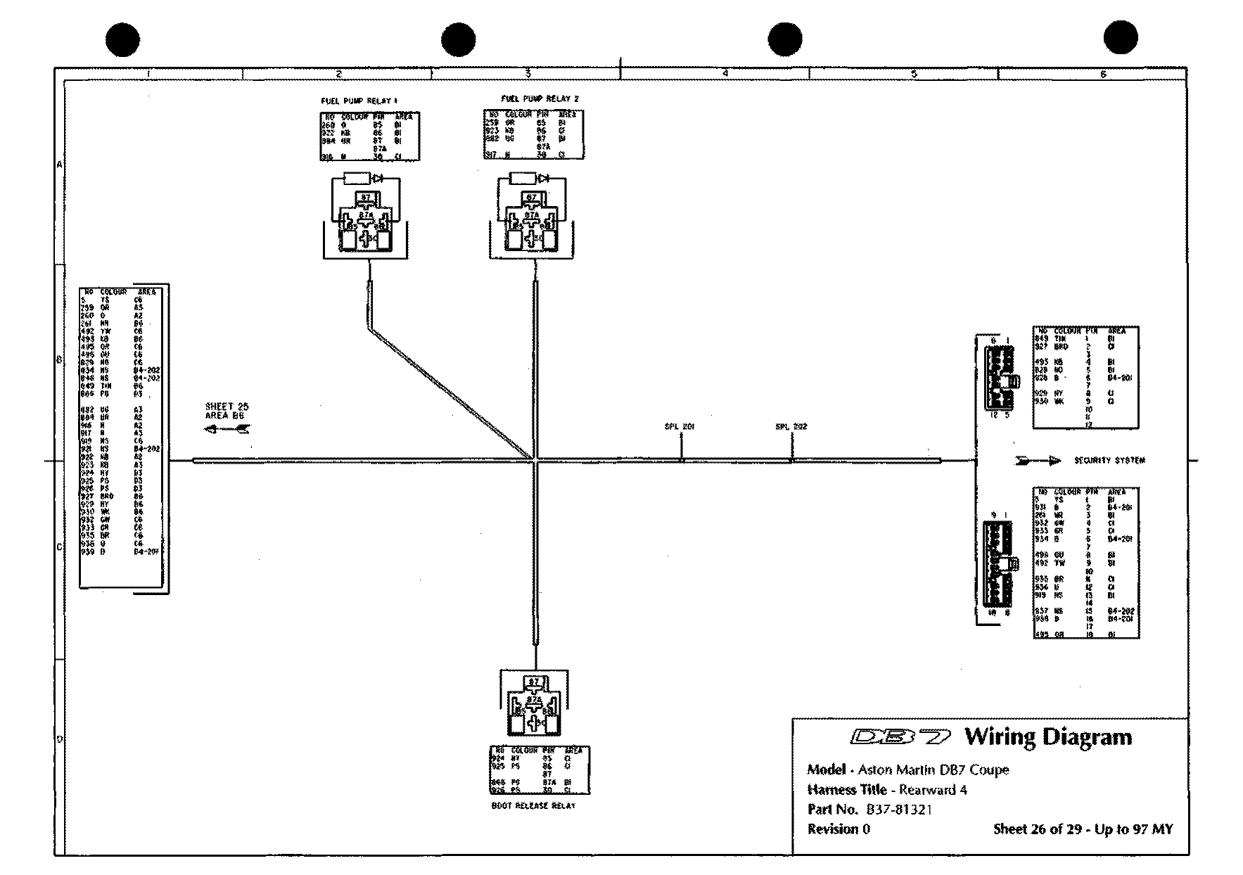
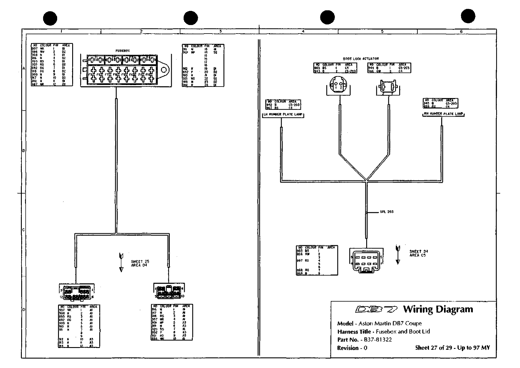
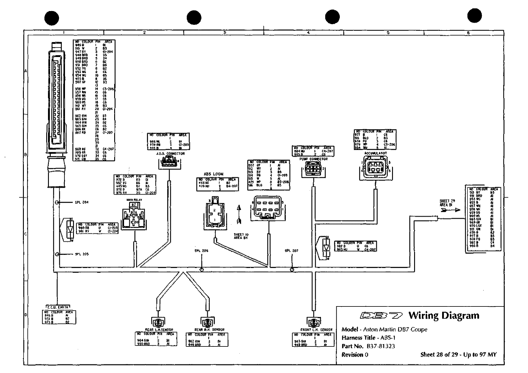
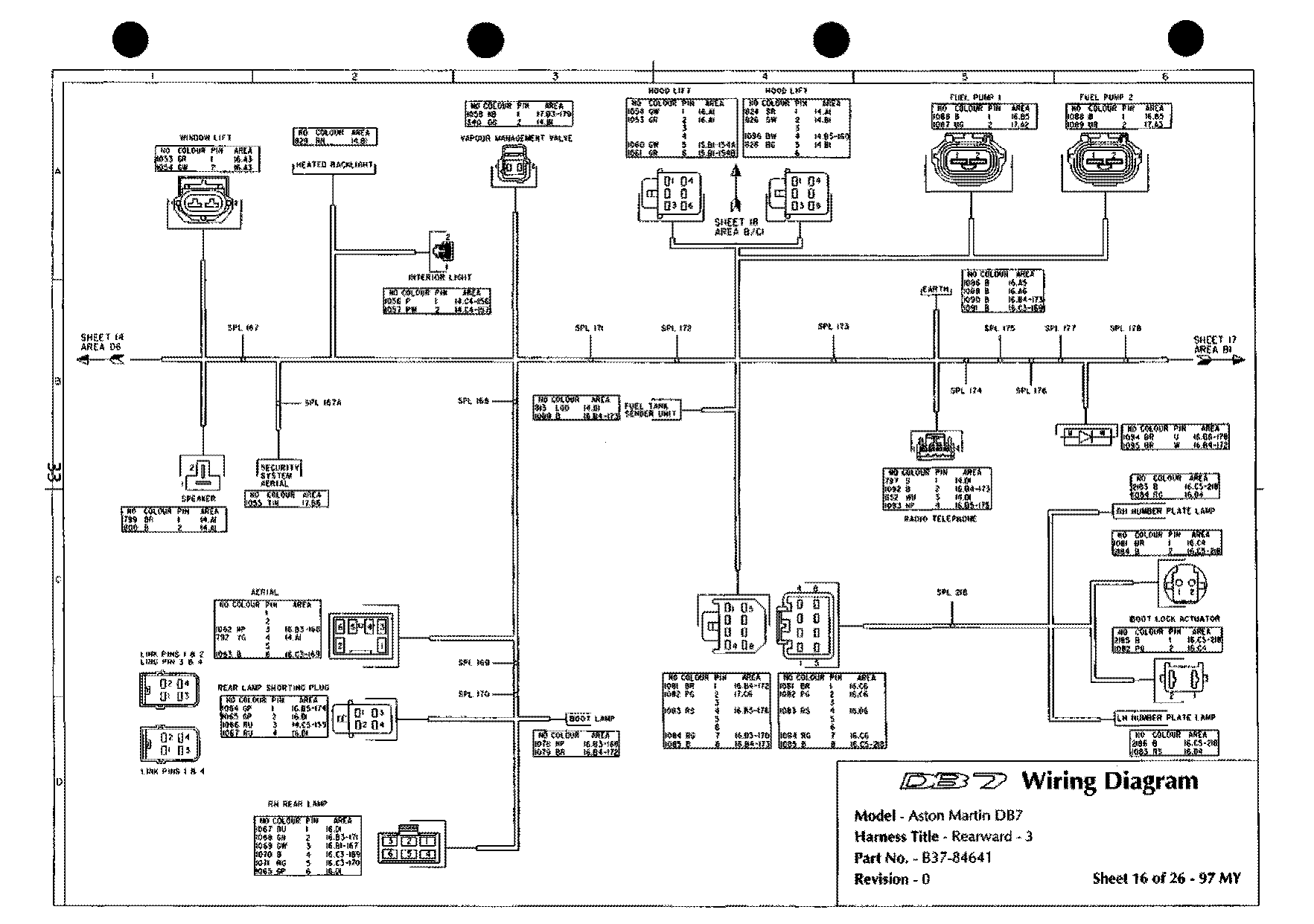
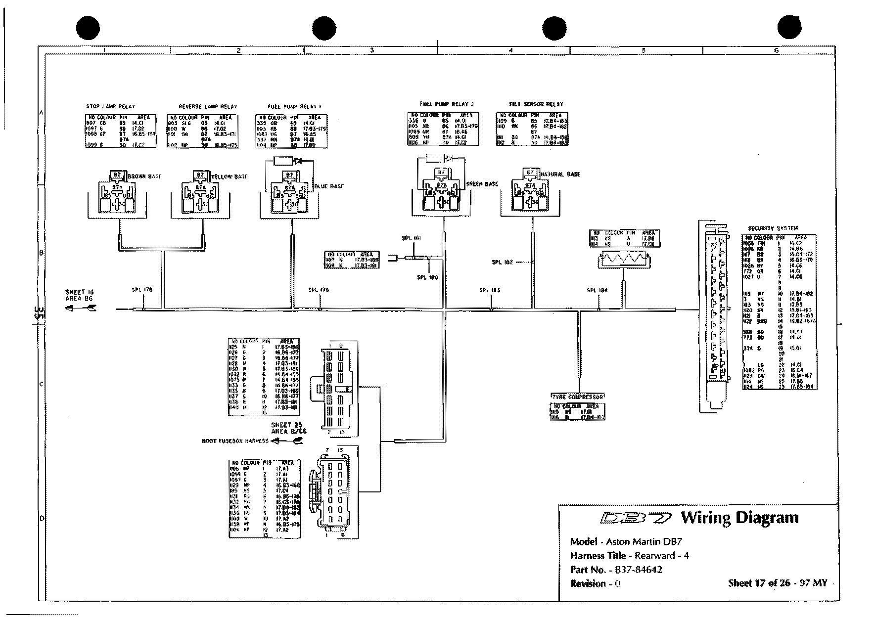
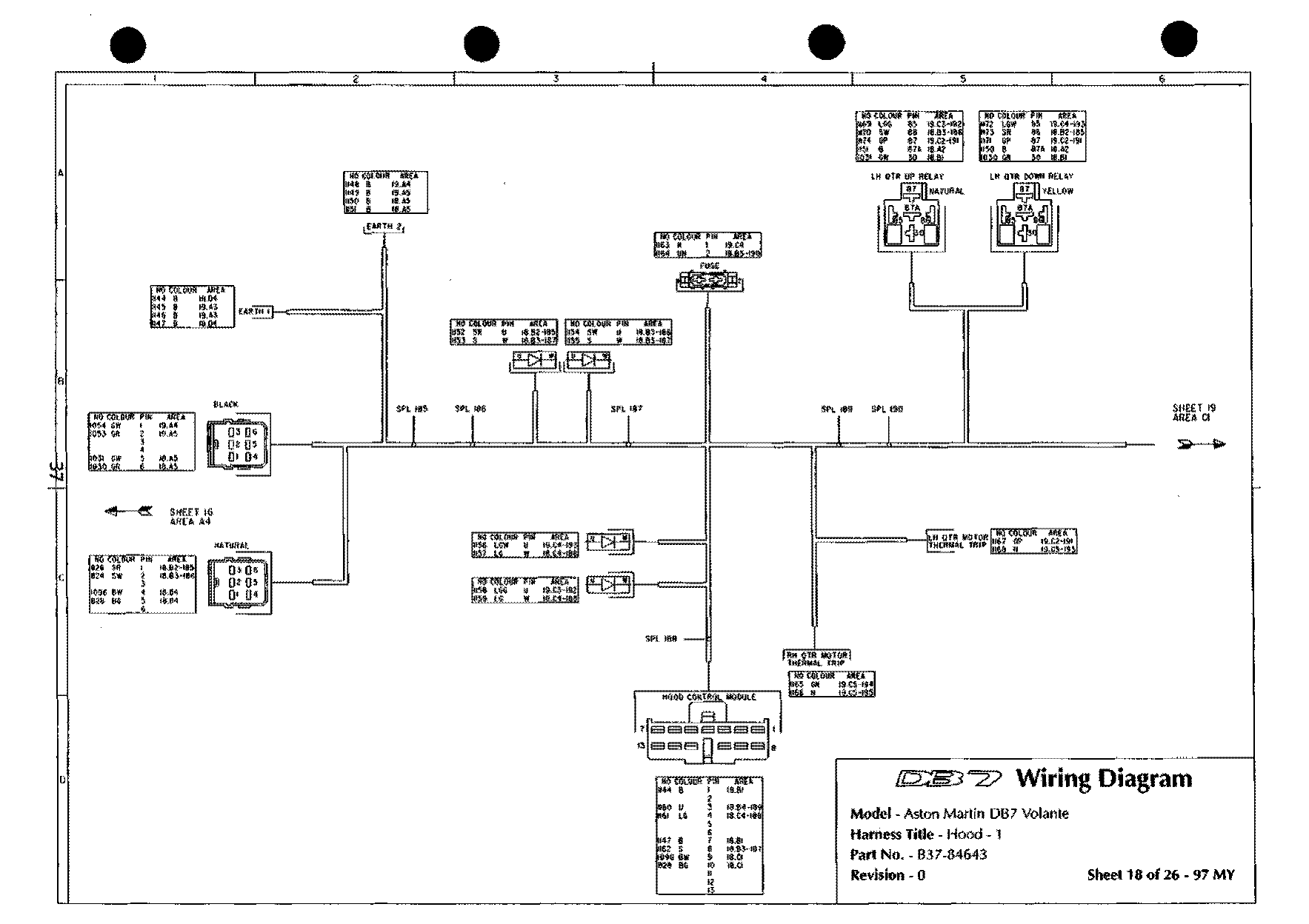
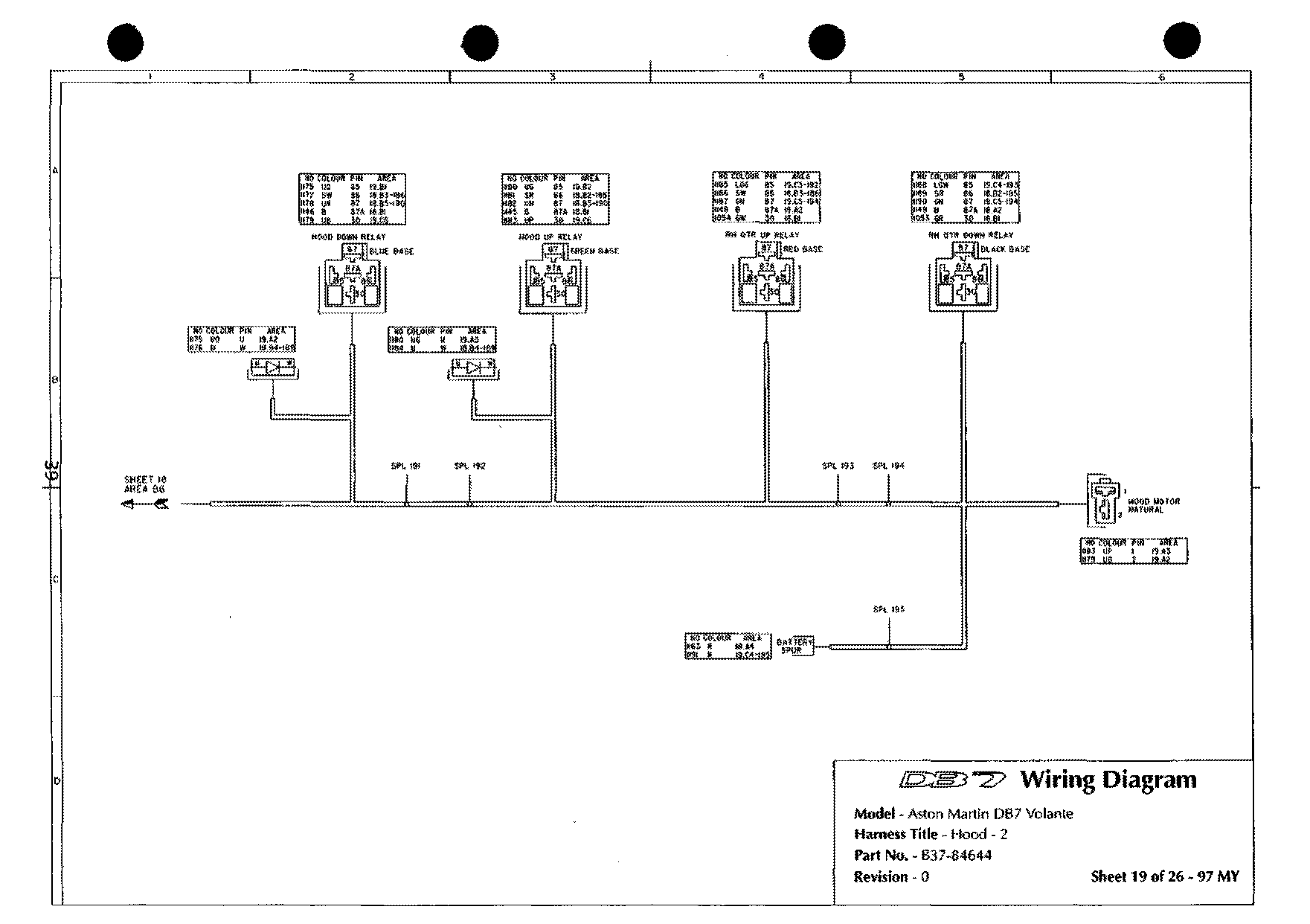
i6 component locations
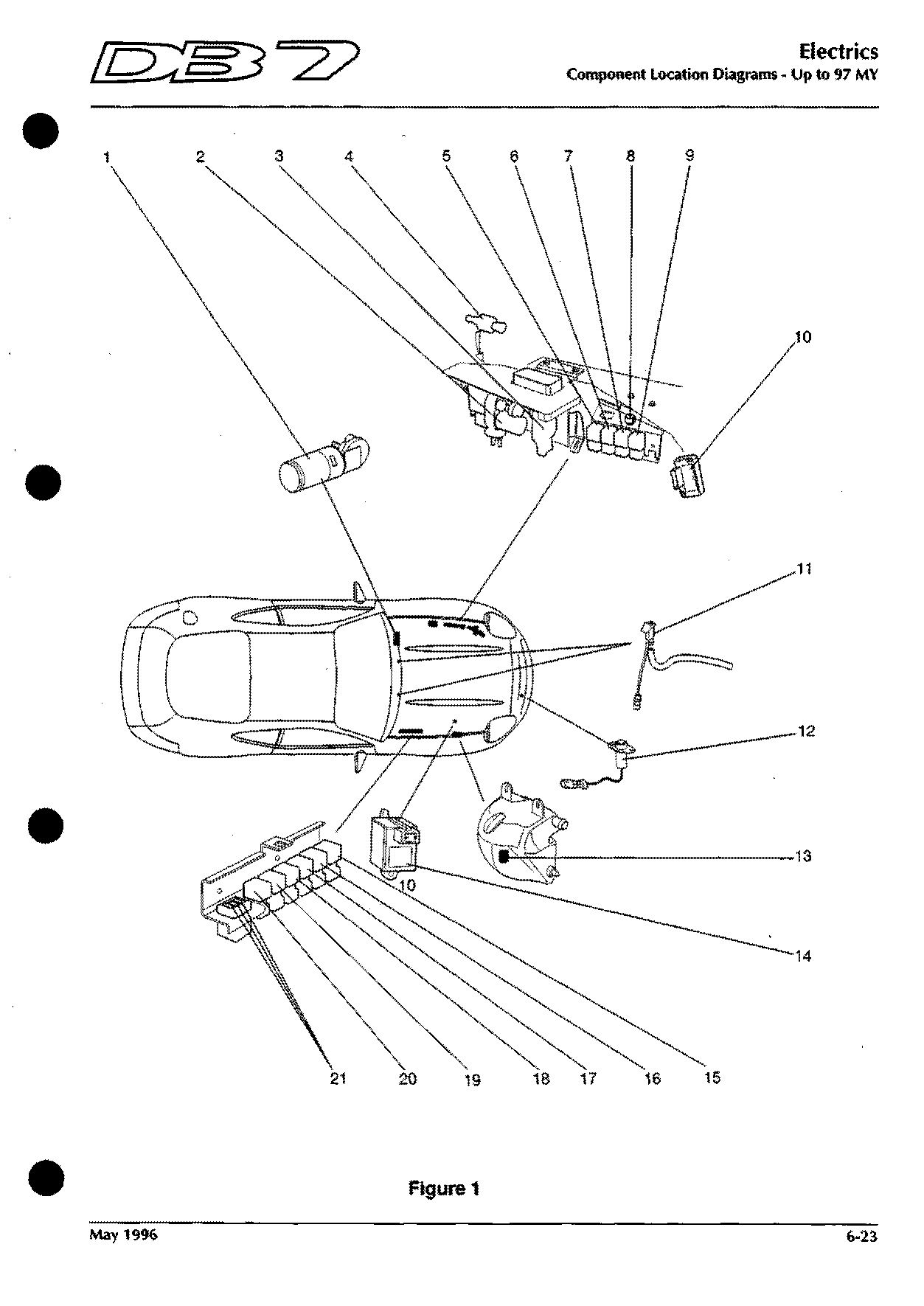
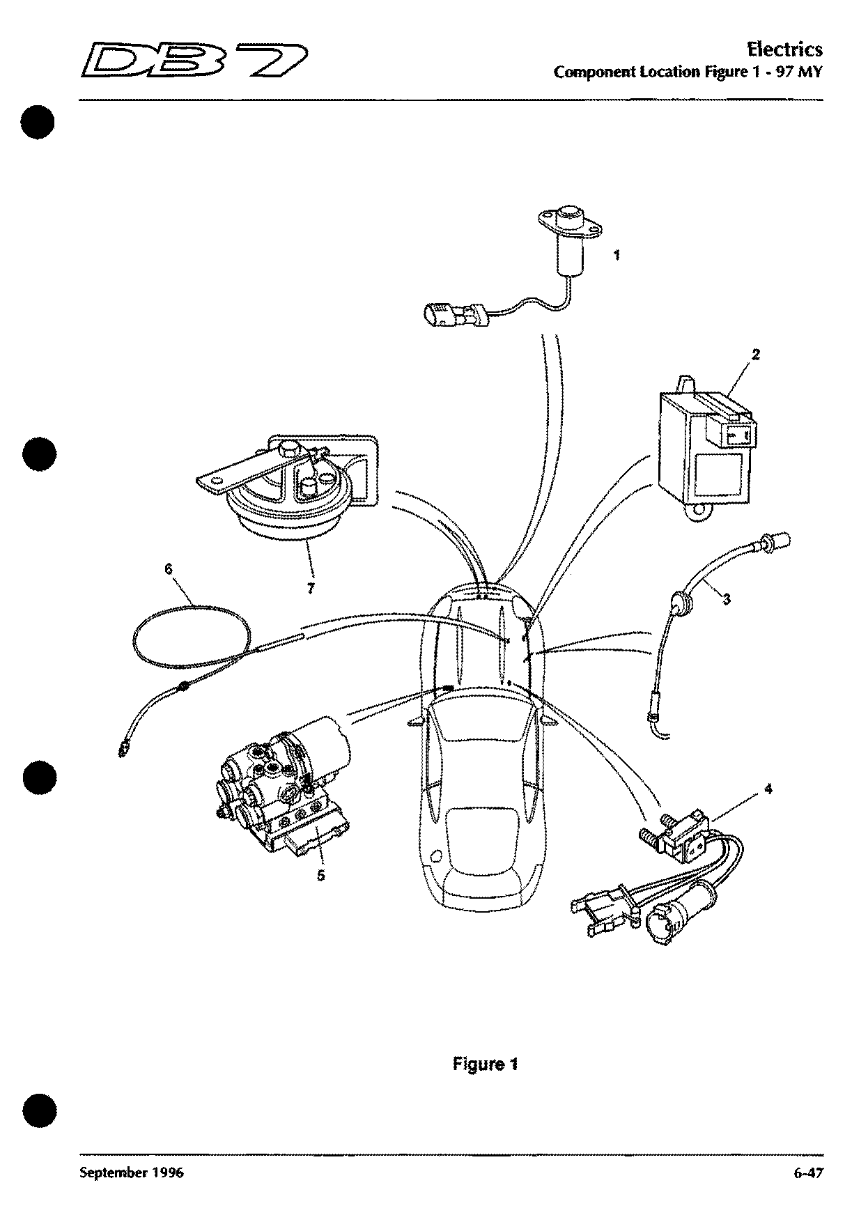
Component locations · up to 97 MY
Figure 1
Shows: Ambient Temperature Sensor, Cruise Control Pump, EDIS Amplifier Module, Fan Fuses, Headlamp Control Module, Heated Washer Jet, Relay - Air conditioning clutch …
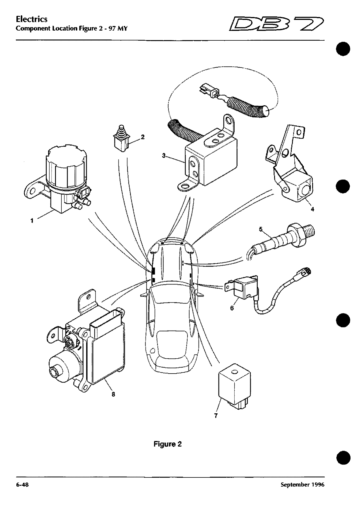
Component locations · up to 97 MY
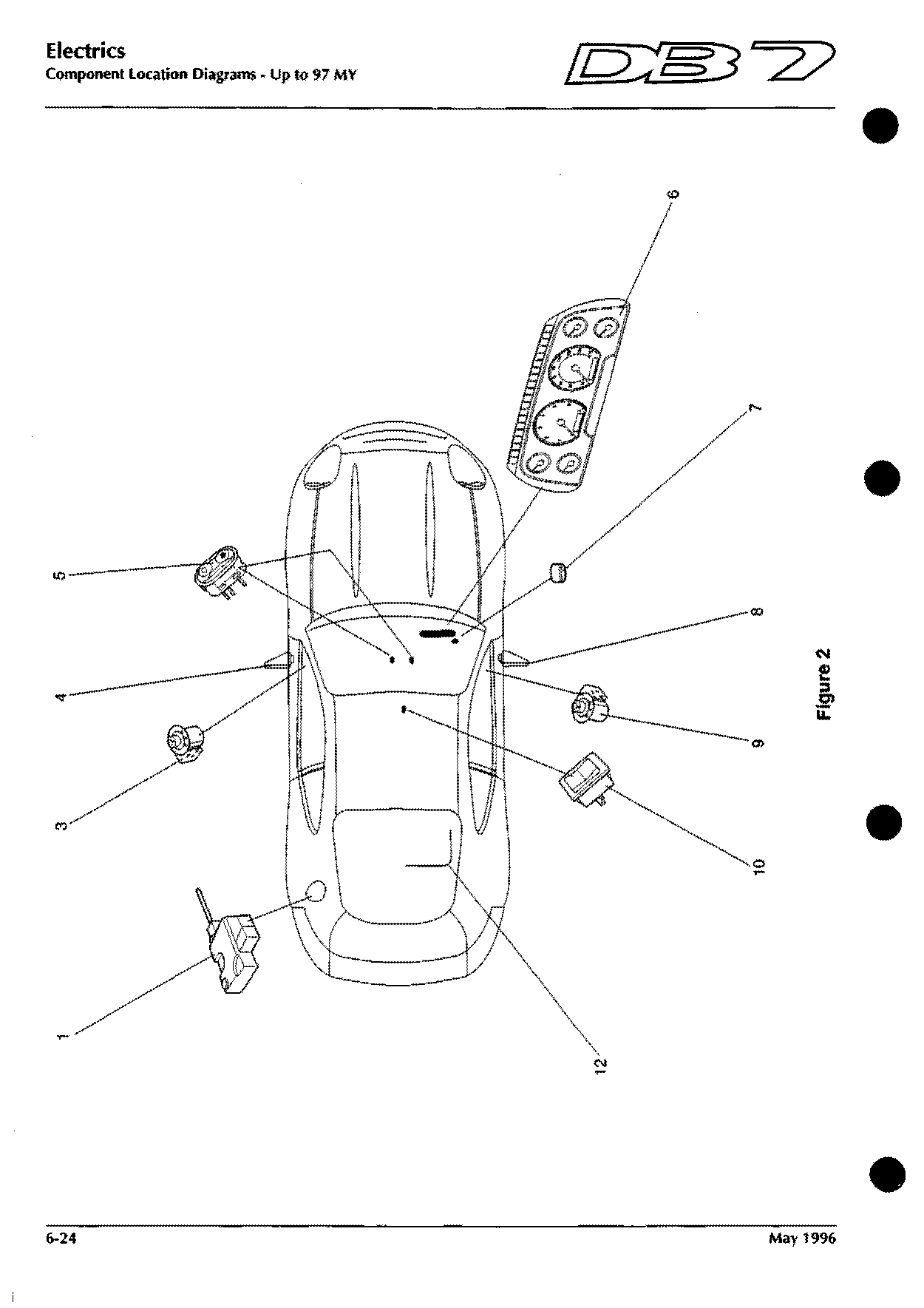
Figure 2
Shows: Boot Release Switch, Door M i r r o r - LHD, Door M i r r o r - RHD, Door Mirror Switch LH, Door Mirror Switch RH, Fuel Filler Flap Solenoid, Instrument Panel Illumination Control …
Component locations · up to 97 MY
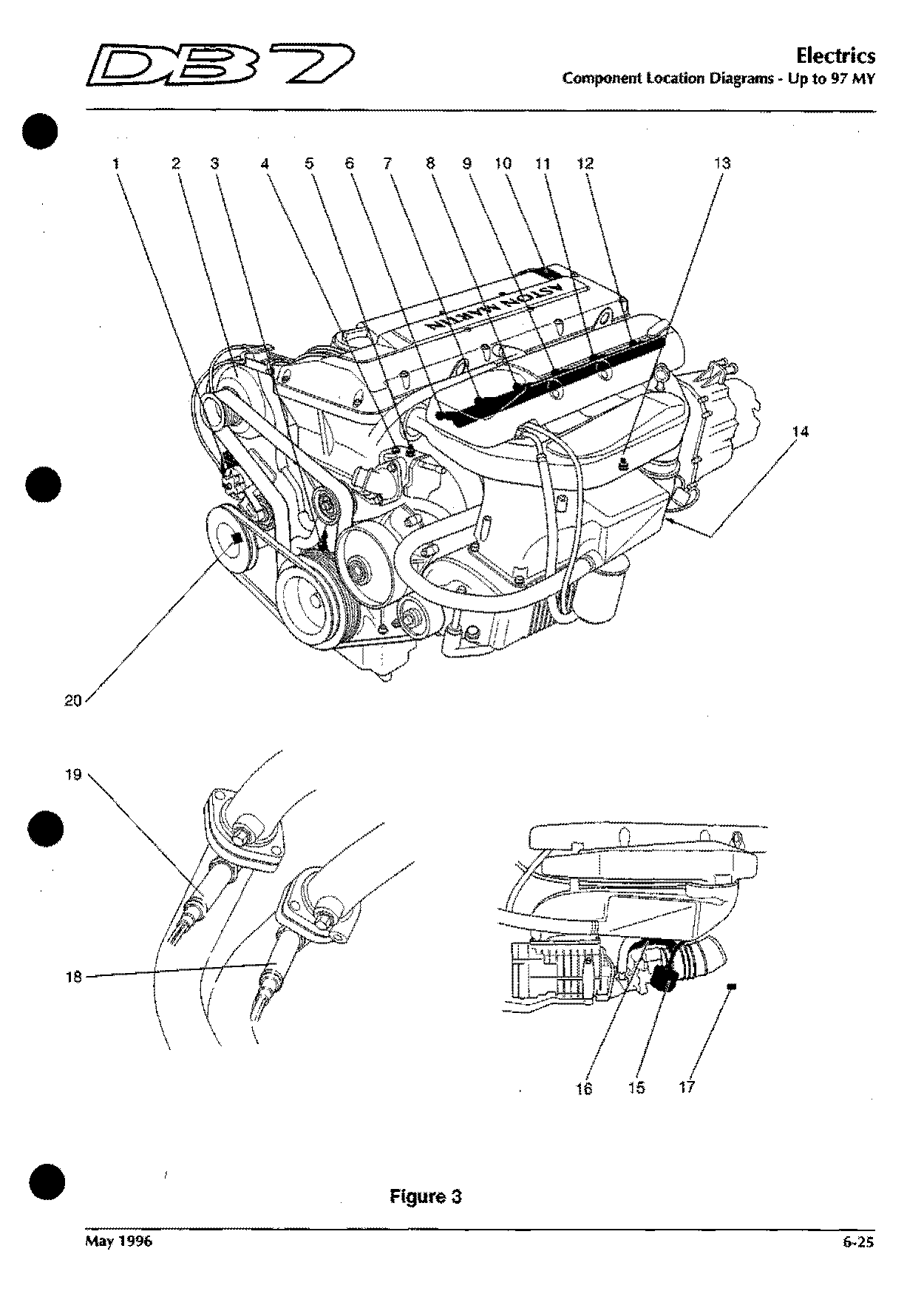
Figure 3
Shows: Air Con Compressor Clutch, Air Temperature Sensor, Alternator, Camshaft Sensor, Crankshaft Position Sensor, EDIS Coil Pack, Idle Speed Control Valve …
Component locations · up to 97 MY
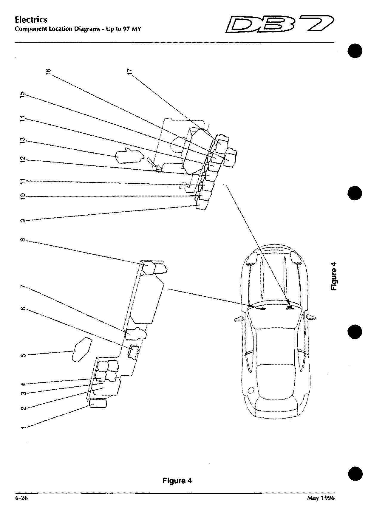
Figure 4
Shows: Bulb Fail Unit - Front Side Lights, Dimmer Module, Exhaust Temperature/Speed Warning, Flasher Module, Multifunction Module, Relay - ABS Pump, Relay - Air Pump …
Component locations · up to 97 MY
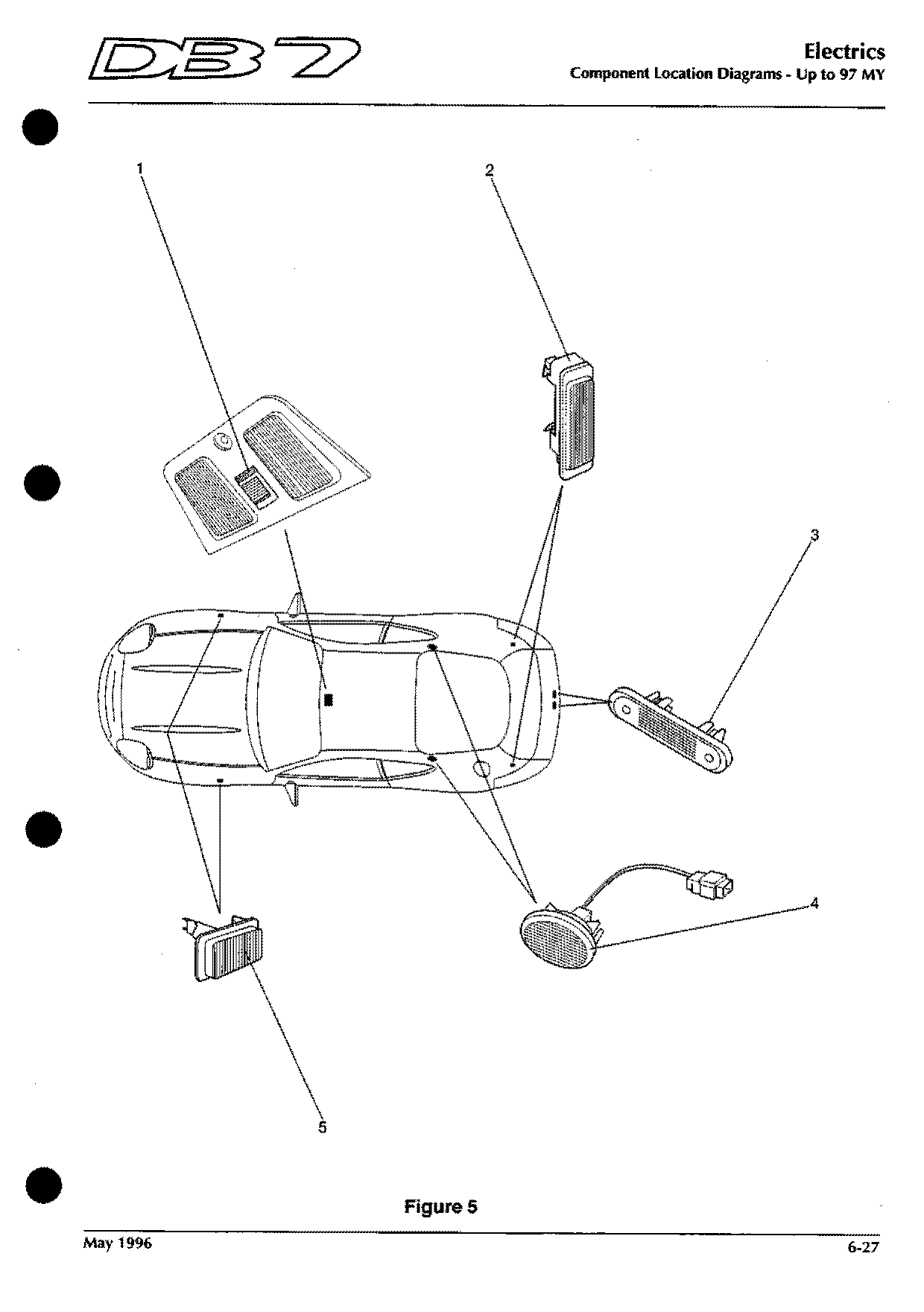
Figure 5
Shows: Boot Lamp, Interior Light - Rear LH, Interior Light - Rear RH, Map Reading Light, Number Plate Lamp - LH, Number Plate Lamp - RH, Side Marker Lamp - LH Front …
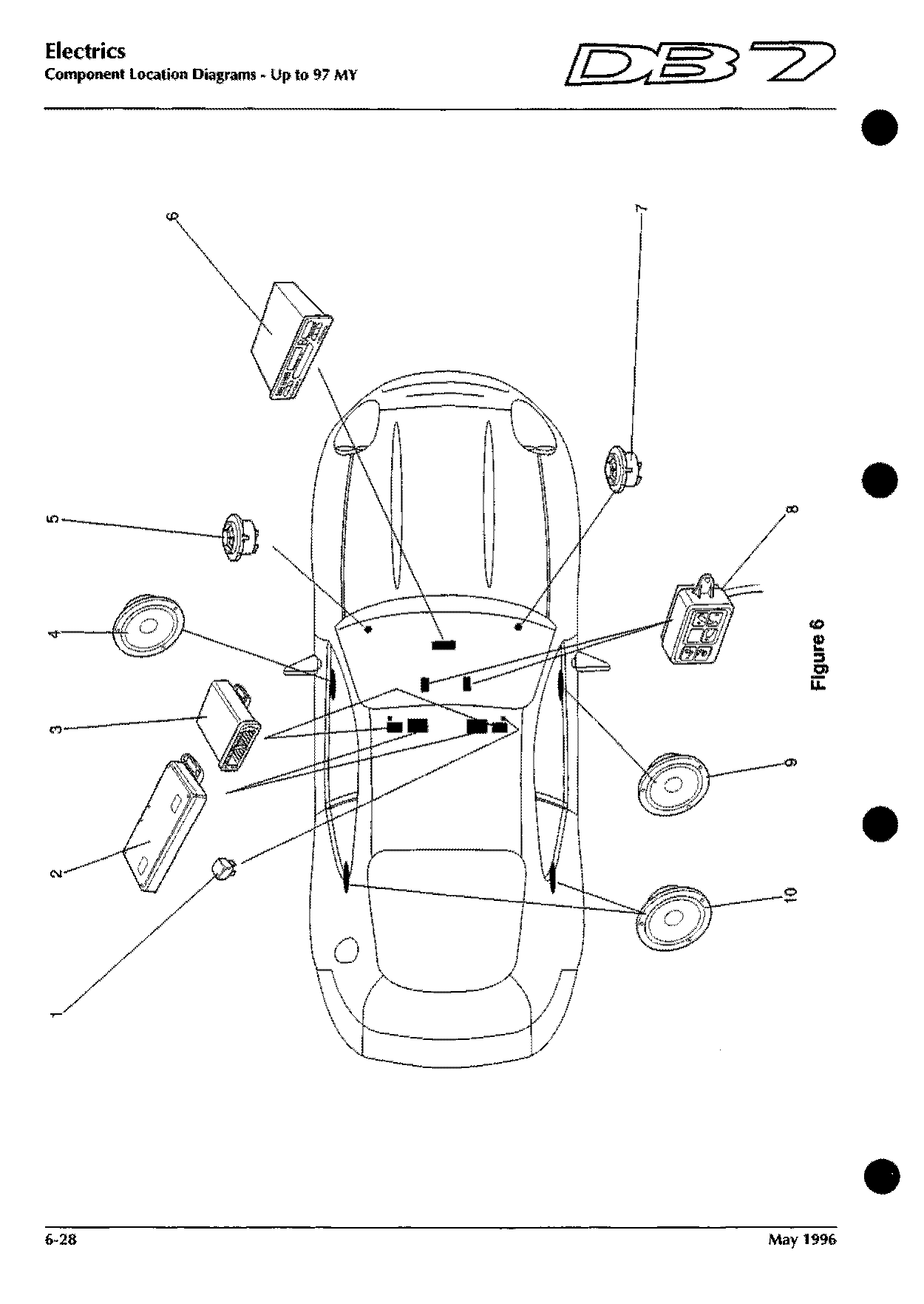
Component locations · up to 97 MY
Figure 6
Shows: Cruise Control ECU, Door Speaker - L H, Door Speaker - RH, Radio Tweeter, Radio, Relay - Cruise Control On/Off, Seat ECU - Driver …
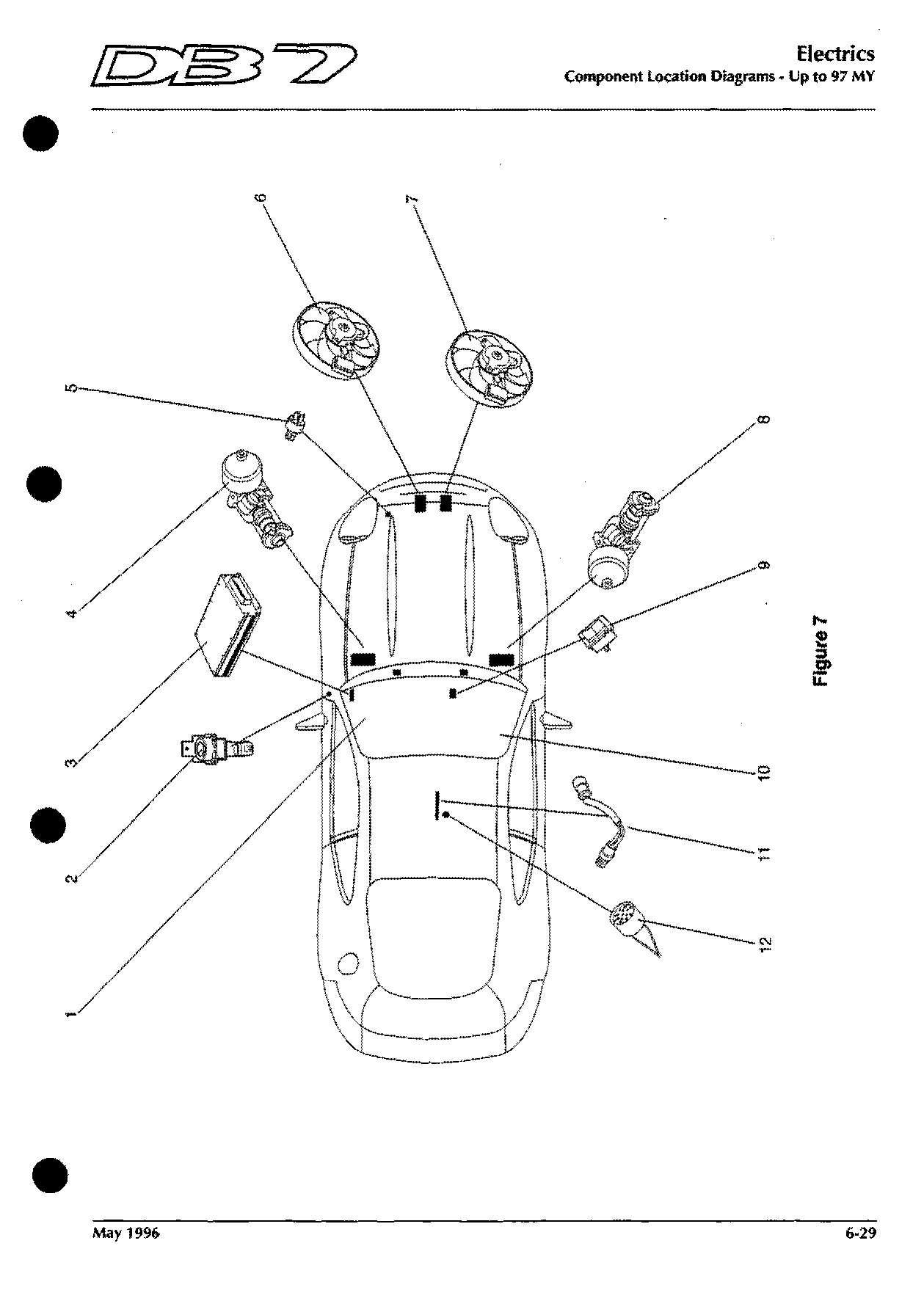
Component locations · up to 97 MY
Figure 7
Shows: Brake Accumulator Pump, Engine ECU, Fan Motor 1, Fan Motor 2, Fan Run-on Switch, Heated Front Screen, Inertia Switch …
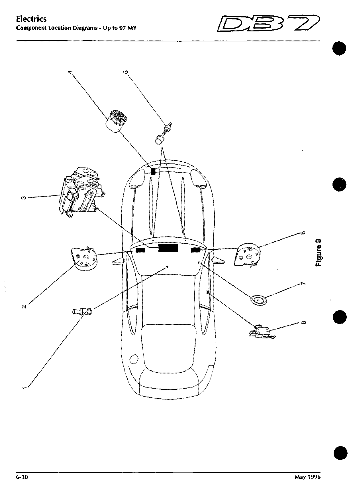
Component locations · up to 97 MY
Figure 8
Shows: Air Con Fan Motor - LH, Air Con Fan Motor - RH, Air Conditioning Unit, Air Pump, Cigar Lighter, Ignition Switch, Kickdown Switch
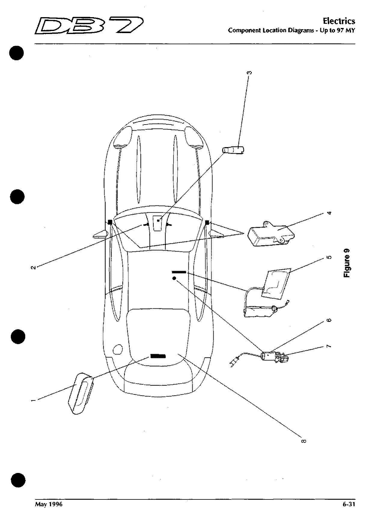
Component locations · up to 97 MY
Figure 9
Shows: Central Locking Unit, Gear Selector Illumination, Heated Rear Screen, High Level Stop Lamp, Logic Earth, Recline Motor Potentiometer, Seat Motor Potentiometer
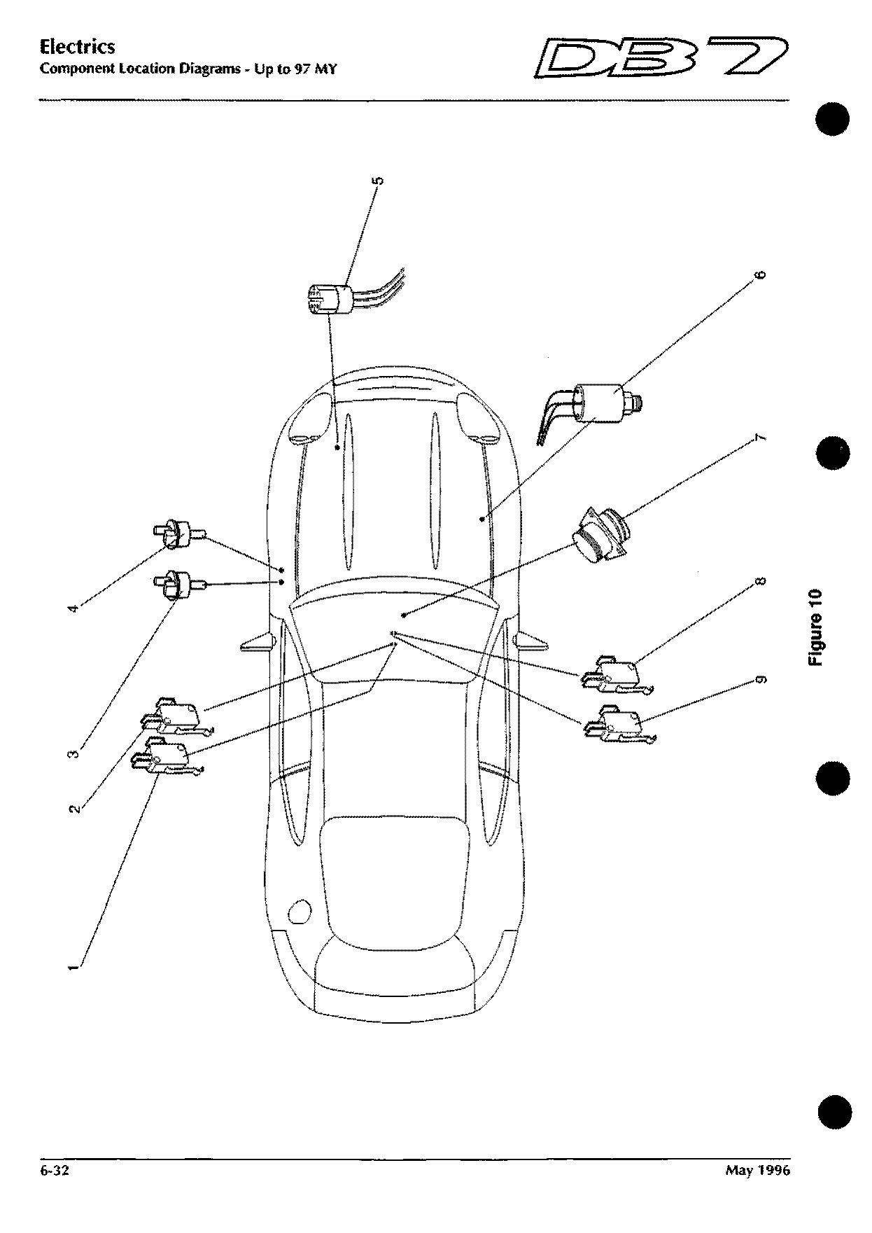
Component locations · up to 97 MY
Figure 10
Shows: Air Conditioning Trinary Switch, Cruise Control Inhibit Switch, Diagnostic Socket - Transmission, Engine Diagnostic Socket, Park Switch (Auto), Purge Valve 1, Purge Valve 2 …
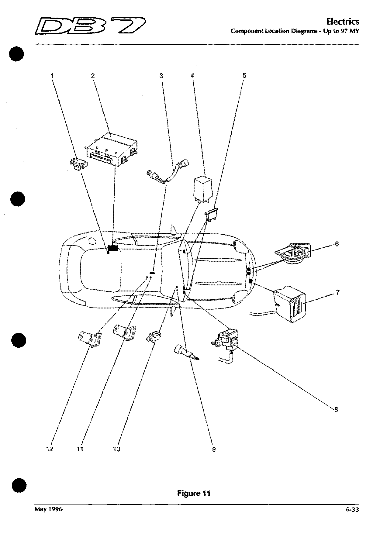
Component locations · up to 97 MY
Figure 11
Shows: Barometric Pressure Sensor, Cruise Control Brake Switch, Gearbox ECU, Heated Front Screen Controller, Heated Front Screen Fuse - 40A, Horn - LH, Horn - RH …
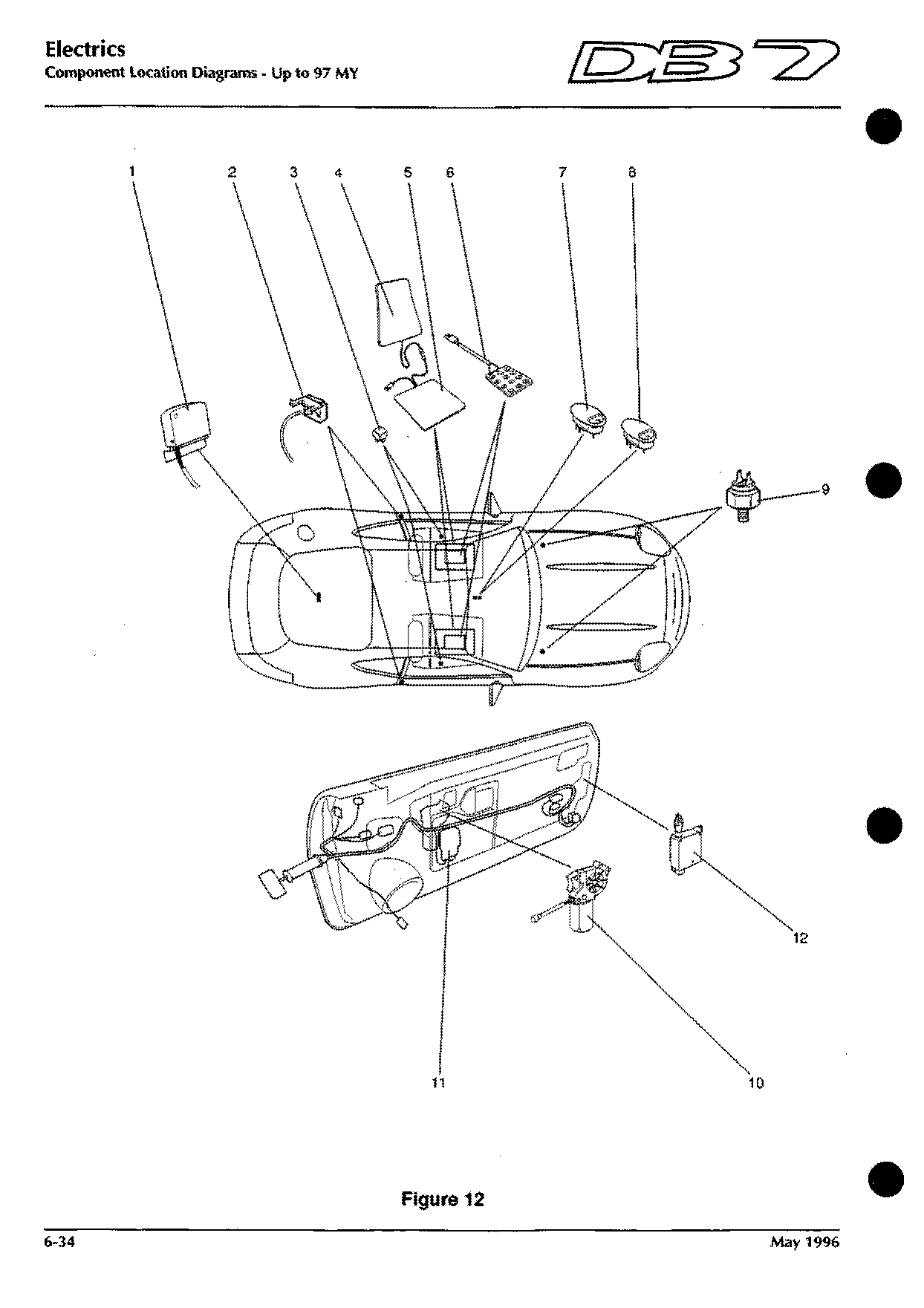
Component locations · up to 97 MY
Figure 12
Shows: Cruise Control Clutch Switch (LHD), Cruise Control On/Off Switch, Cruise Control Set Switch, Door Lock Actuator, Microswitch - Glass Drop LH, Microswitch - Glass Drop RH, Microwave Sensor …
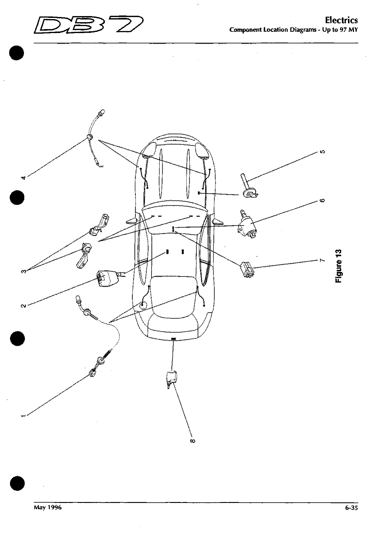
Component locations · up to 97 MY
Figure 13
Shows: Boot Lock Actuator, Column Switchgear, Gear Shift Interlock Solenoid, Gearshift Interlock Module, Low Coolant Probe, Seat Belt Switch, Wheel Speed Sensor - Front RH …
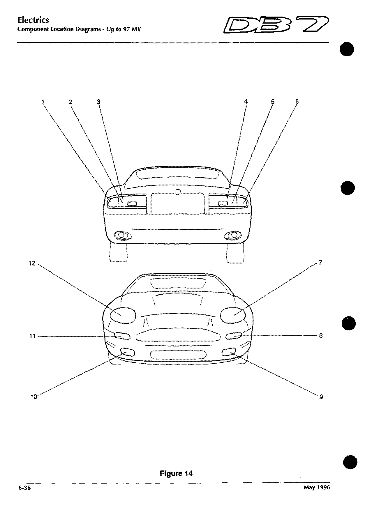
Component locations · up to 97 MY
Figure 14
Shows: Fog Lamp - RH Front, Fog Lamp - LH Front, Head/Side Lamp - LH Front, Head/Side Lamp - RH Front, Indicator/Side Lamp - LH Front, Indicator/Side Lamp - RH Front, Rear Fog Lamp LH
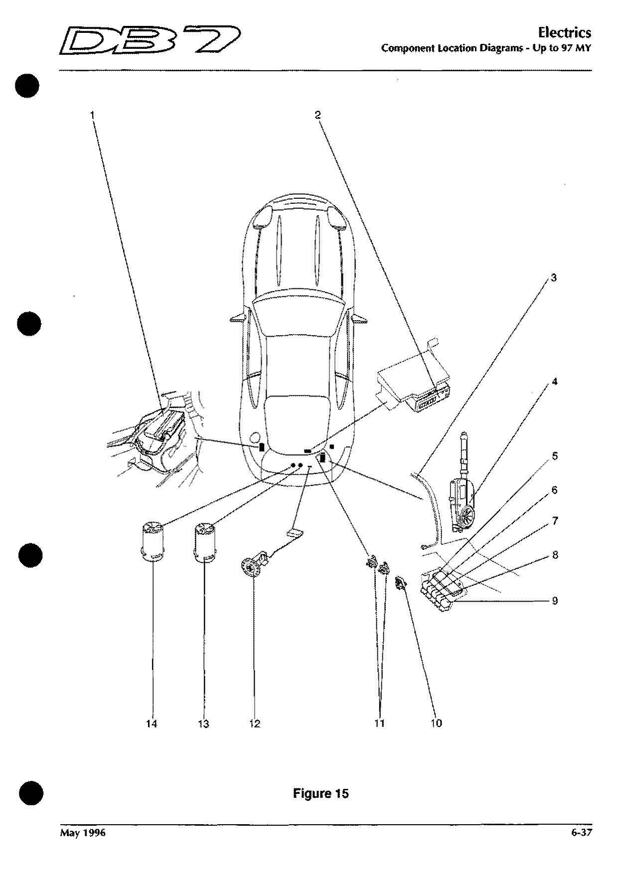
Component locations · up to 97 MY
Figure 15
Shows: ABS ECU, Fuel Pump 1, Fuel Pump 2, Fuel Tank Sender Unit, Radio Aerial, Radio Telephone Connector, Rear & Number Plate Bulb Fail Unit …
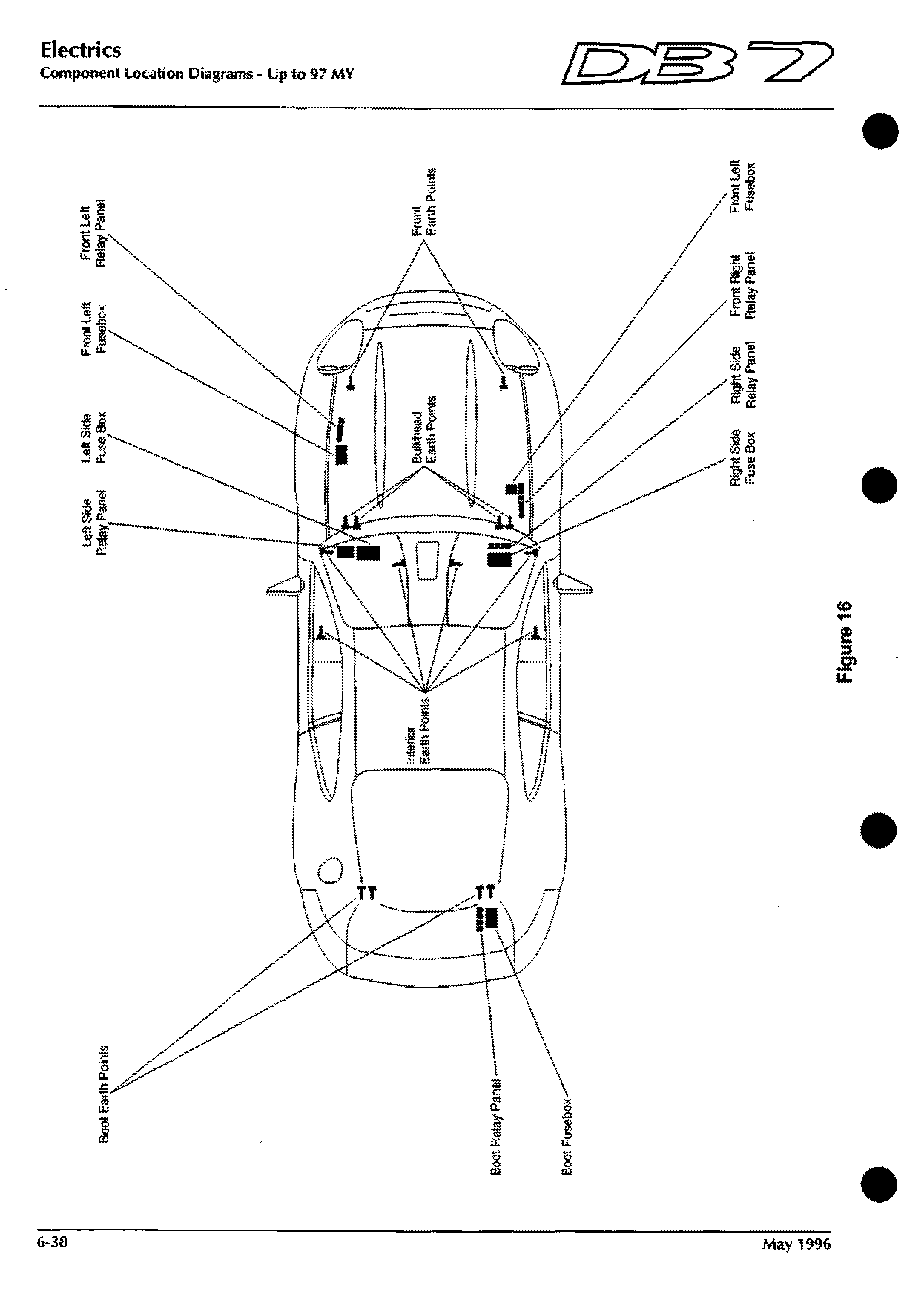
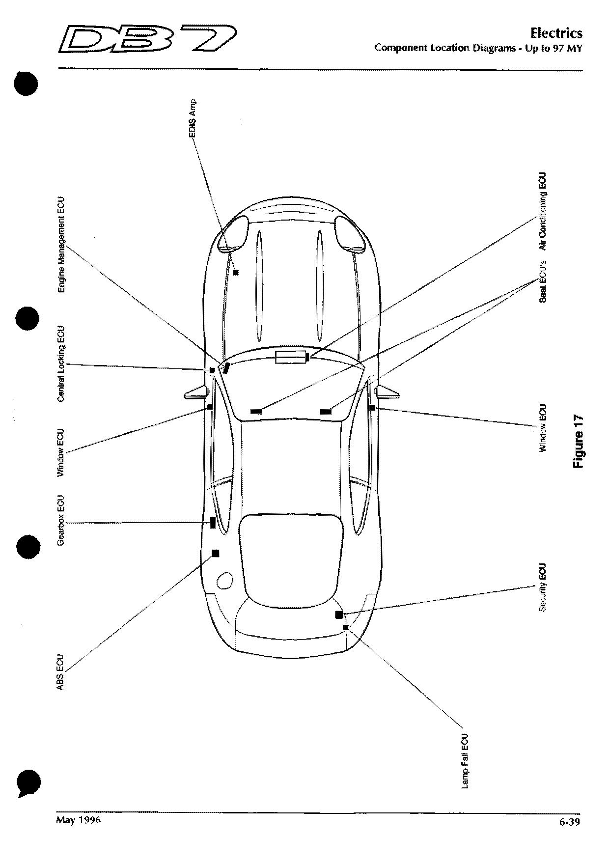
Component locations · 97 MY on
Figure 1
Shows: ABS ECU, ABS Wheel Speed Sensor - Front RH, ABS Wheel Speed Sensor - Front LH, Ambient Temperature Sensor, Capacitor (Generator), Cruise Control Disable and Stop Lamp Switch, Exhaust Temperature/Speed Warning …
Component locations · 97 MY on
Figure 2
Shows: Bonnet Switch, Cruise Control Servo Unit, EVR Valve, Fan Control Module, Heated Oxygen Sensor 1 -1, Heated Oxygen Sensor 1 -2
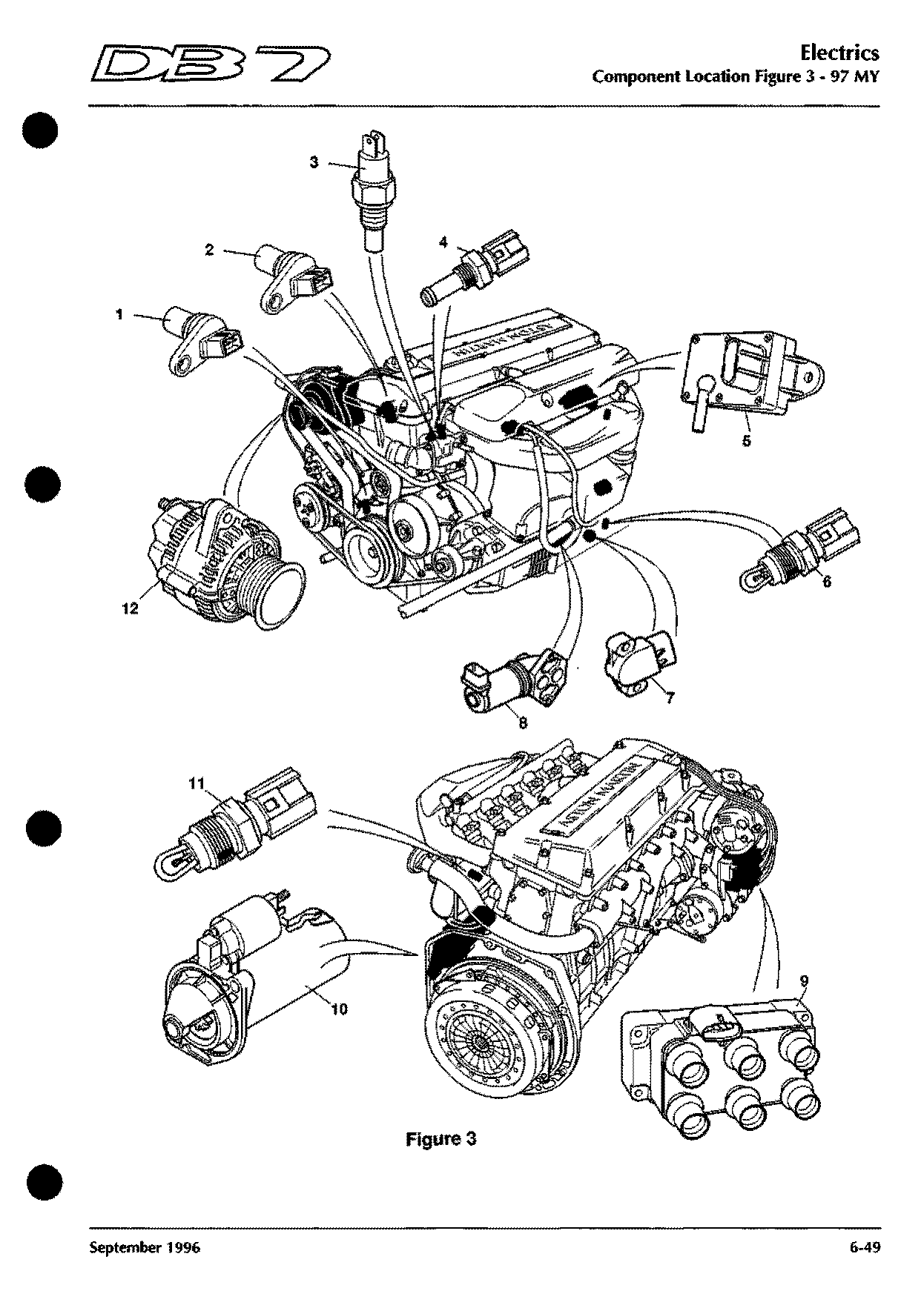
Component locations · 97 MY on
Figure 3
Shows: Air Temperature Sensor (IAT1), Air Temperature Sensor (IAT2), Alternator (Generator), Camshaft Sensor (CMP), Coolant Temperature Sensor (ECT), Coolant Temperature Sensor - Temp Gauge, Crankshaft Position Sensor (CKP) …
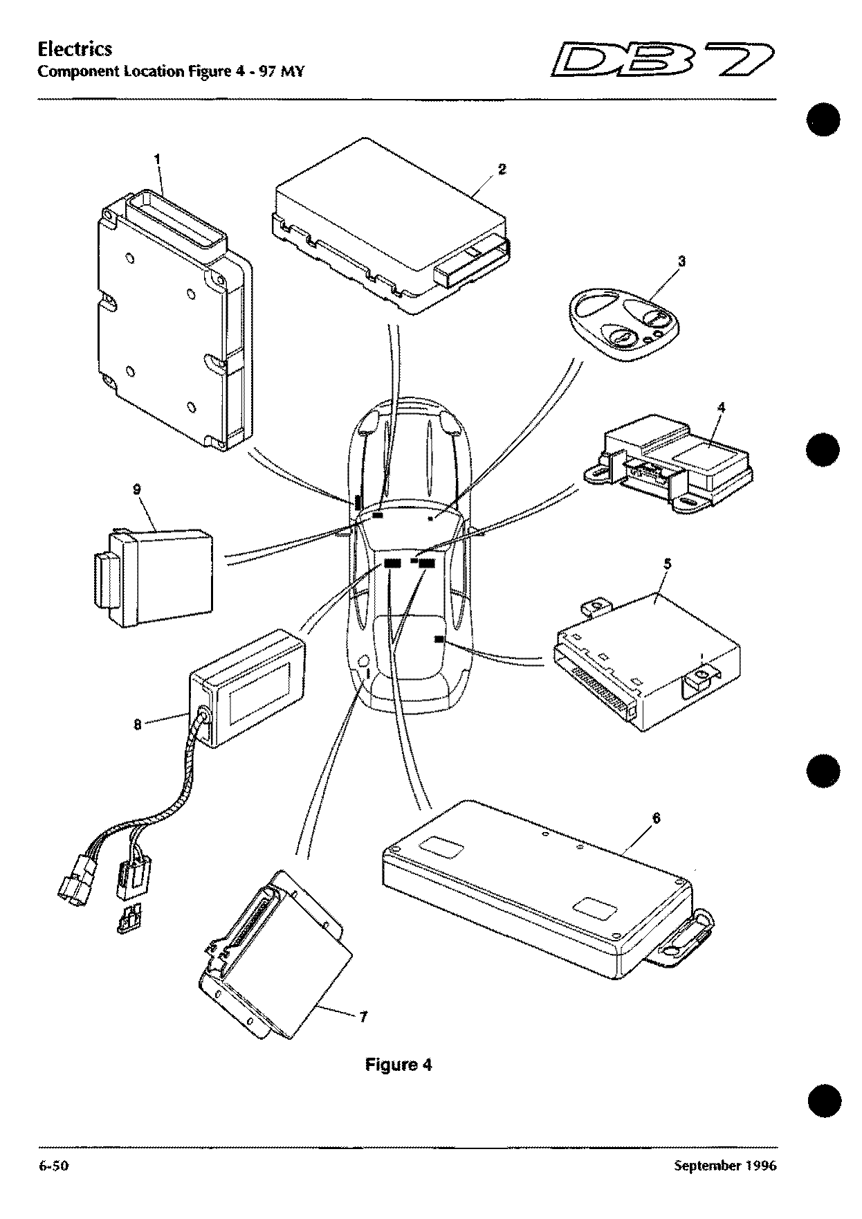
Component locations · 97 MY on
Figure 4
Shows: Catalyst Overtemperature/Speed Warning Module, Powertrain Control Module (PCM), Seat ECU - Driver, Seat ECU - Passenger, Transmission Control Module (TCM)
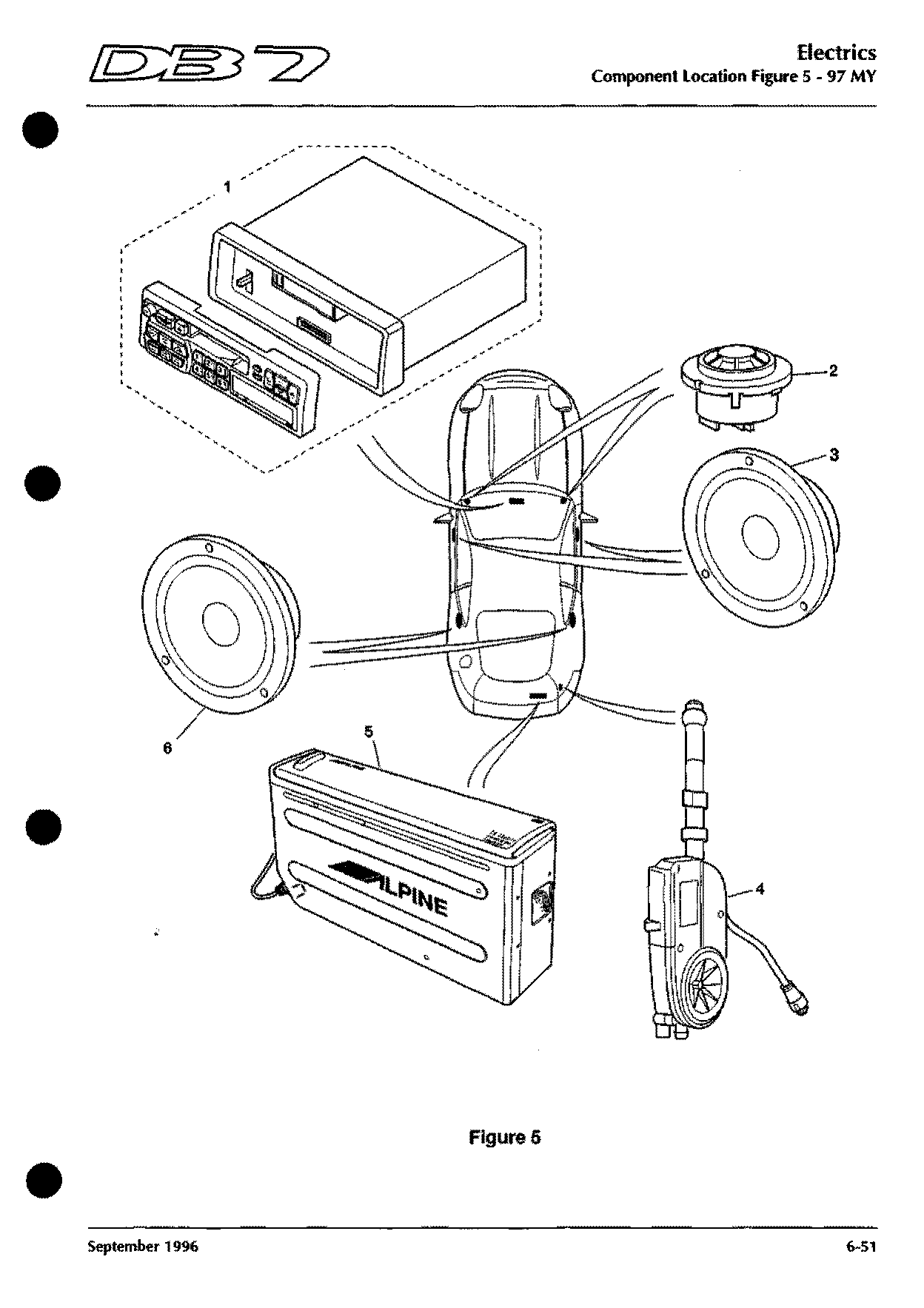
Component locations · 97 MY on
Figure 5
Shows: CD Autochanger, Radio, Radio Aerial, Radio Tweeter (LH), Radio Tweeter (RH), Speaker - Drivers Door, Speaker - Passengers Door …
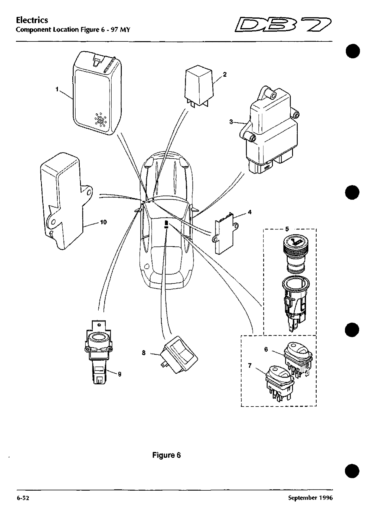
Component locations · 97 MY on
Figure 6
Shows: Central Locking Unit, Cigar Lighter, Cruise Control On/Off Switch, Cruise Control Set Switch, Inertia Switch, Multifunction Module, Performance Mode Switch …
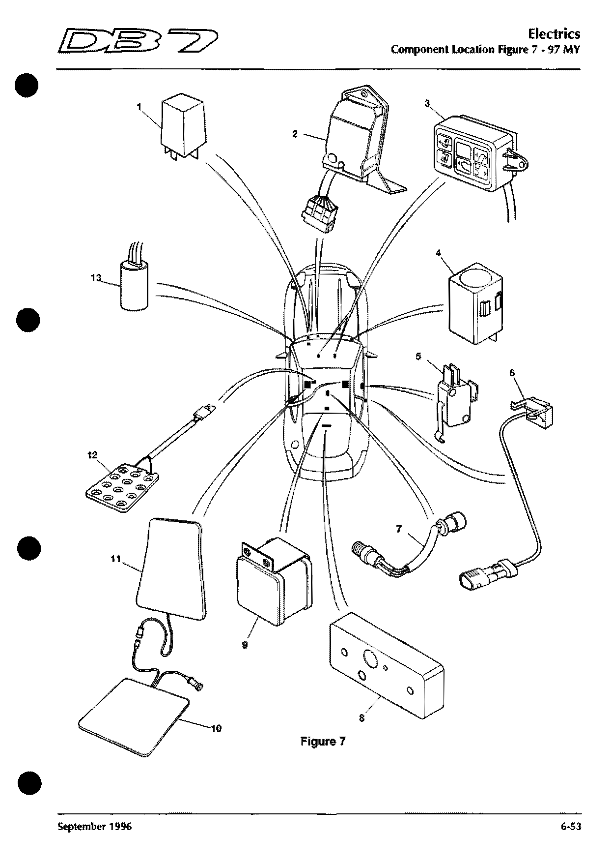
Component locations · 97 MY on
Figure 7
Shows: Door Closed Microswitch (Drivers), Door Closed Microswitch (Passengers), Handbrake Switch, Instrument Panel Illumination Control, Low Coolant Signal Transmitter, Reversing Light Switch, Seat Heater Cushion Element …
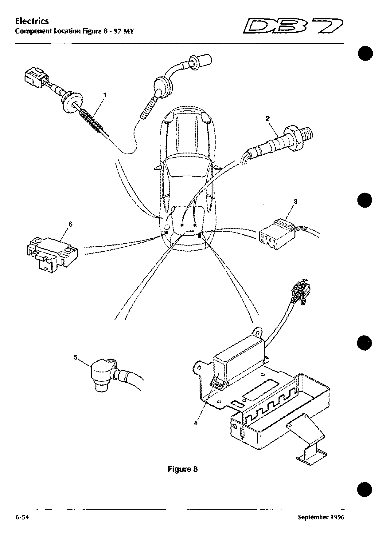
Component locations · 97 MY on
Figure 8
Shows: ABS Wheel Speed Sensor - Rear RH, ABS Wheel Speed Sensor - Rear LH, Barometric Pressure Sensor, Heated Oxygen Sensor 2-1, Heated Oxygen Sensor 2-2, Hood Control Module (Volante Roof), Radio Telephone Connector …
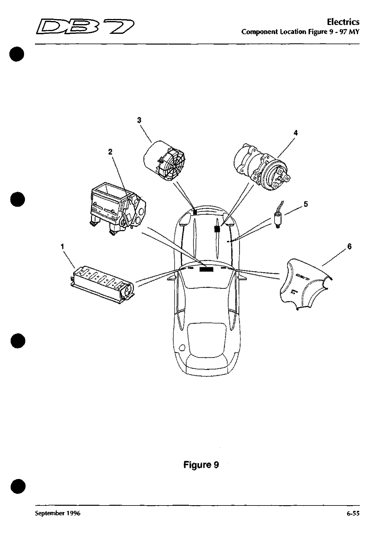
Component locations · 97 MY on
Figure 9
Shows: Air Conditioning Compressor Clutch, Air Conditioning Control, Air Conditioning Trinary Switch, Air Conditioning Unit, Air Pump
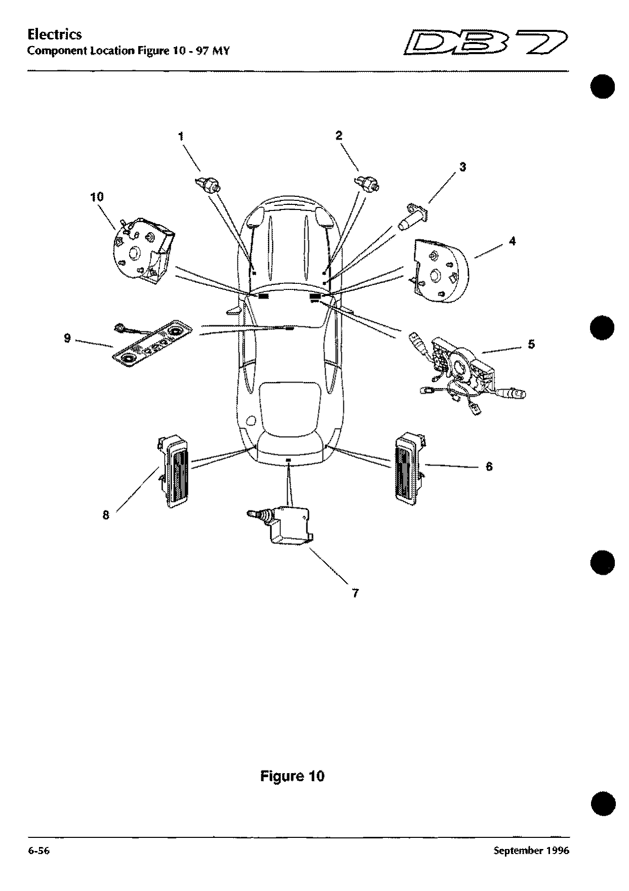
Component locations · 97 MY on
Figure 10
Shows: Blower Fan LH, Blower Fan RH, Boot Lamp LH, Boot Lamp RH, Boot Lock Actuator, Column Switchgear Assembly, Coolant Low Level Sensor …
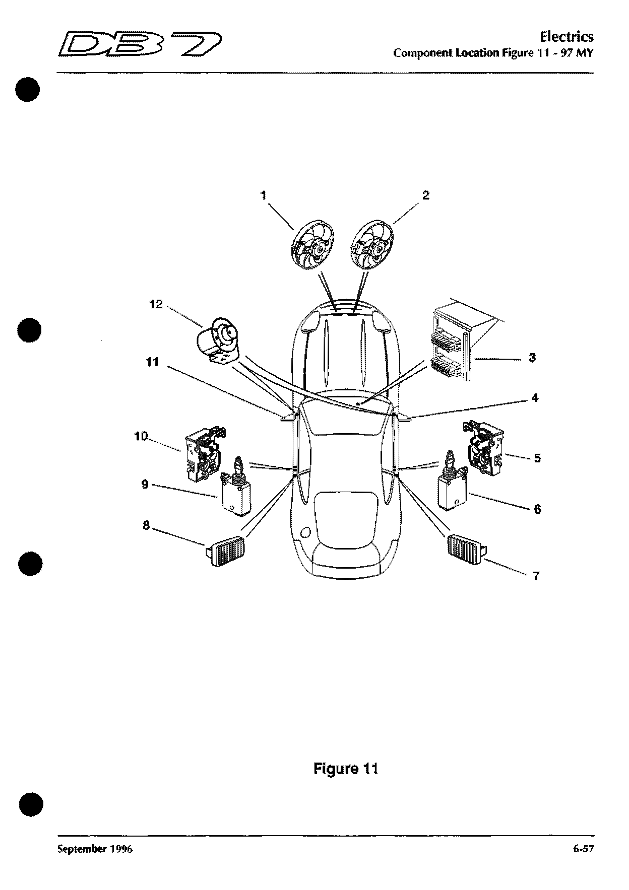
Component locations · 97 MY on
Figure 11
Shows: Diagnostic Socket - Lower, Diagnostic Socket - Upper, Door Lock Motor (Drivers), Door Lock Motor (Passengers), Door Lock Switch (Drivers), Door Lock Switch (Passengers), Door Mirror - (Passengers) …
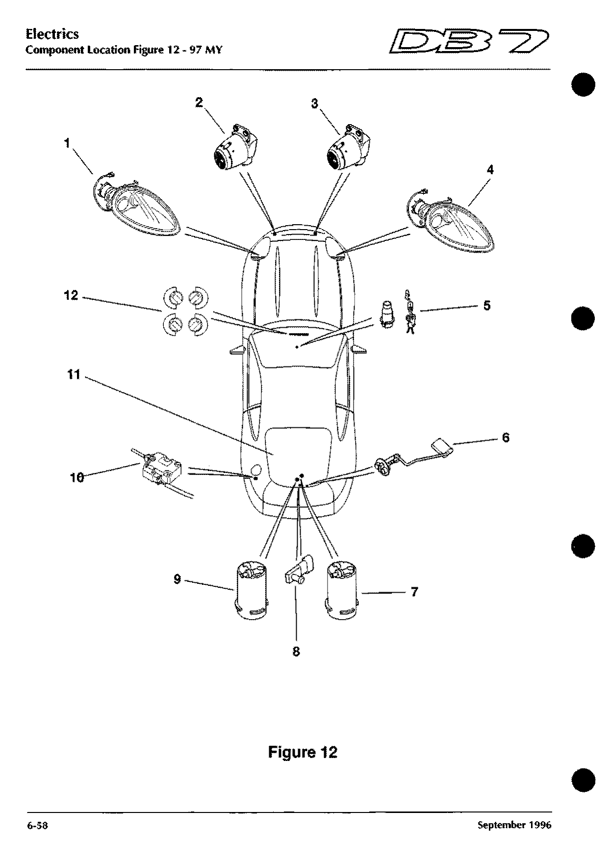
Component locations · 97 MY on
Figure 12
Shows: Foglamp - RH Front, Foglamp - LH Front, Fuel Filler Flap Solenoid, Fuel Pump 1, Fuel Pump 2, Fuel Tank Pressure Sensor, Fuel Tank Sender Unit …
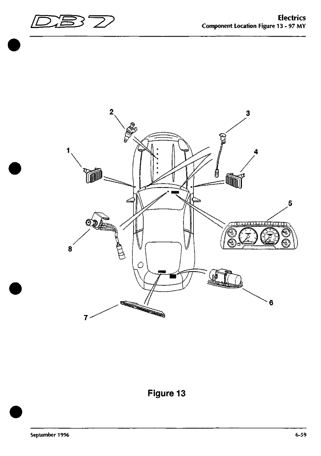
Component locations · 97 MY on
Figure 13
Shows: Heated Washer Jet LH, Heated Washer Jet RH, High Level Stop Lamp, Hood Motor (Volante Roof), Injector 1, Injector 2, Injector 3 …
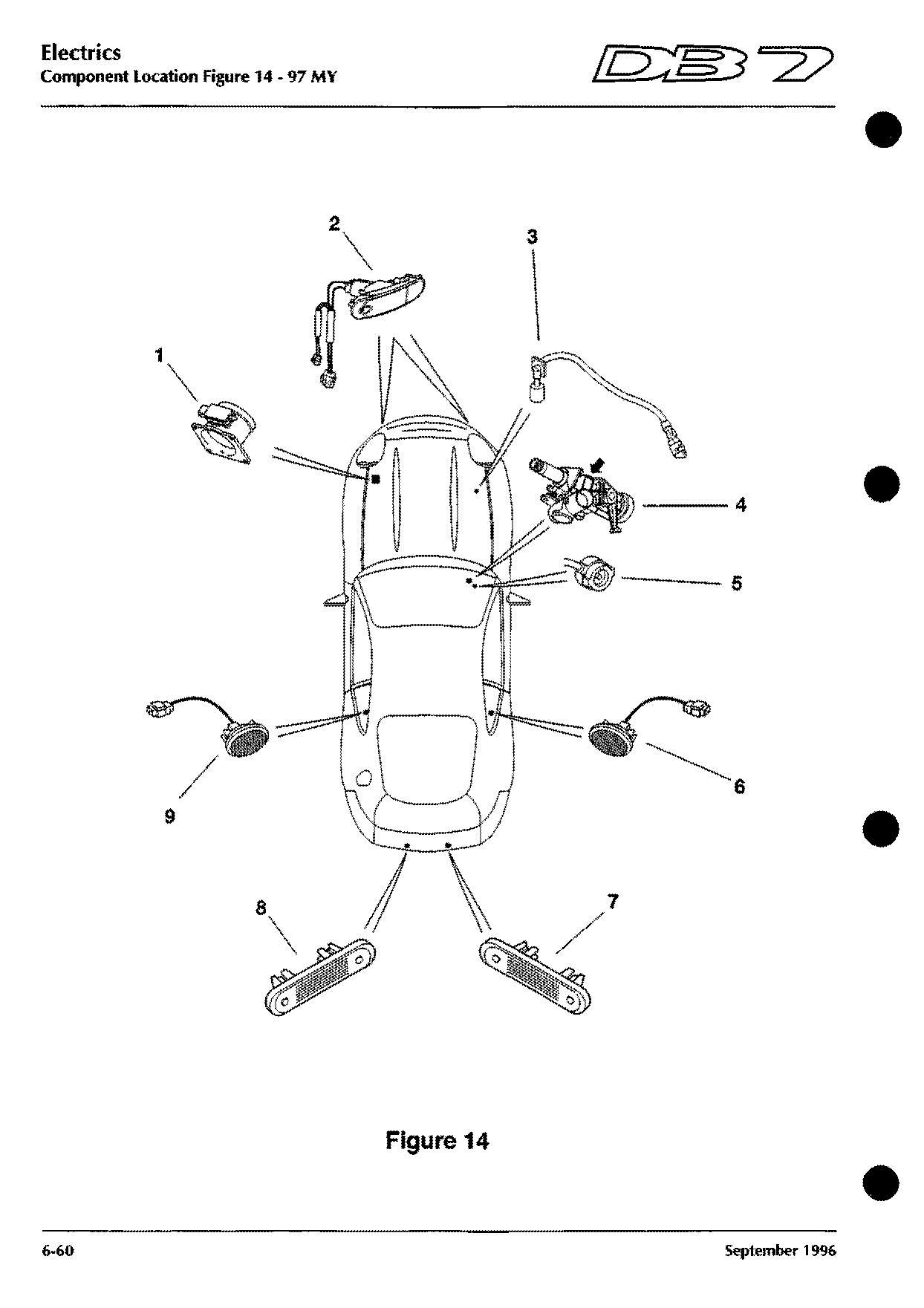
Component locations · 97 MY on
Figure 14
Shows: Ignition Switch, Indicator/Side Lamp - LH Front, Indicator/Side Lamp - RH Front, Interior Light - Rear LH, Interior Light - Rear RH, Key Solenoid, Key-In Warning Switch …
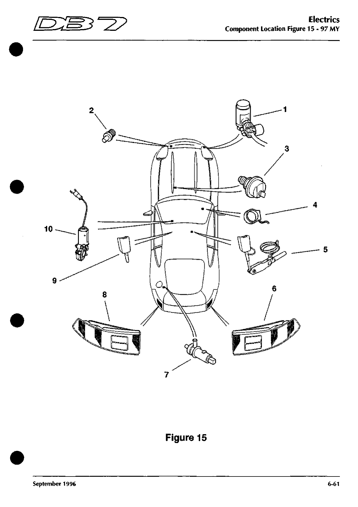
Component locations · 97 MY on
Figure 15
Shows: Oil Pressure Transducer (EOP), Purge Cannister Vent Valve, Radiator Switch, Rear Lamp - LH, Rear Lamp - RH, Screen Wash Pump, Seat Belt Stalk …
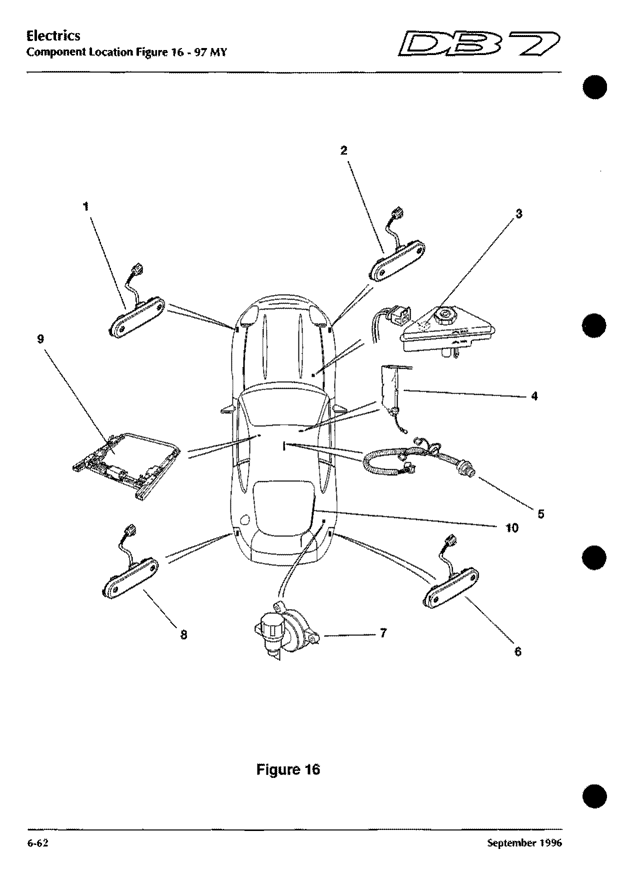
Component locations · 97 MY on
Figure 16
Shows: Brake Fluid Level Sensor, Seat Lumbar Support Pump, Side Marker Lamp - LH Front, Side Marker Lamp - RH Front, Side Marker Lamp - LH Rear, Side Marker Lamp - RH Rear, Transmission Connector
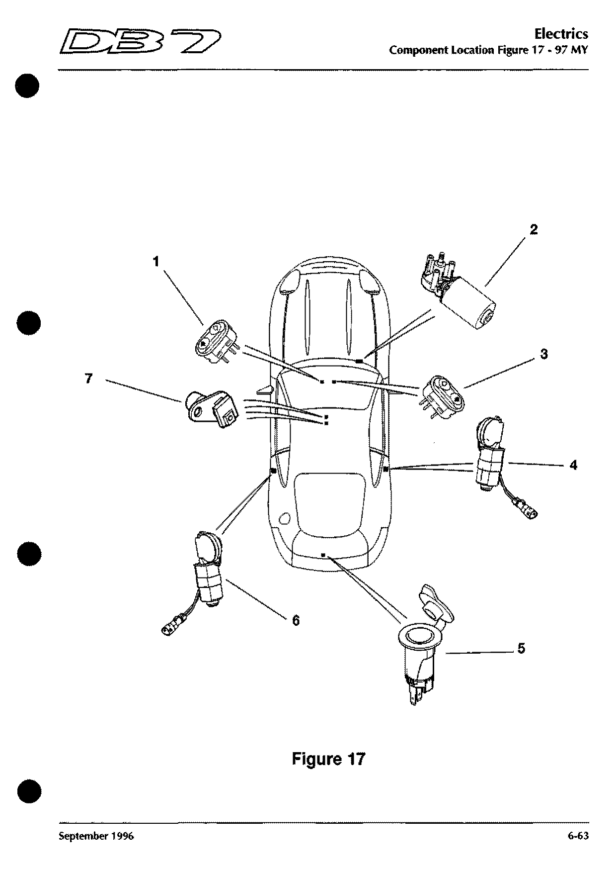
Component locations · 97 MY on
Figure 17
Shows: Transmission Input Speed Sensor, Transmission Output Speed Sensor, Tyre Compressor Socket, Window Lift - Left Quarter Light (Volante), Window Switch LH, Window Switch RH, Wiper Motor
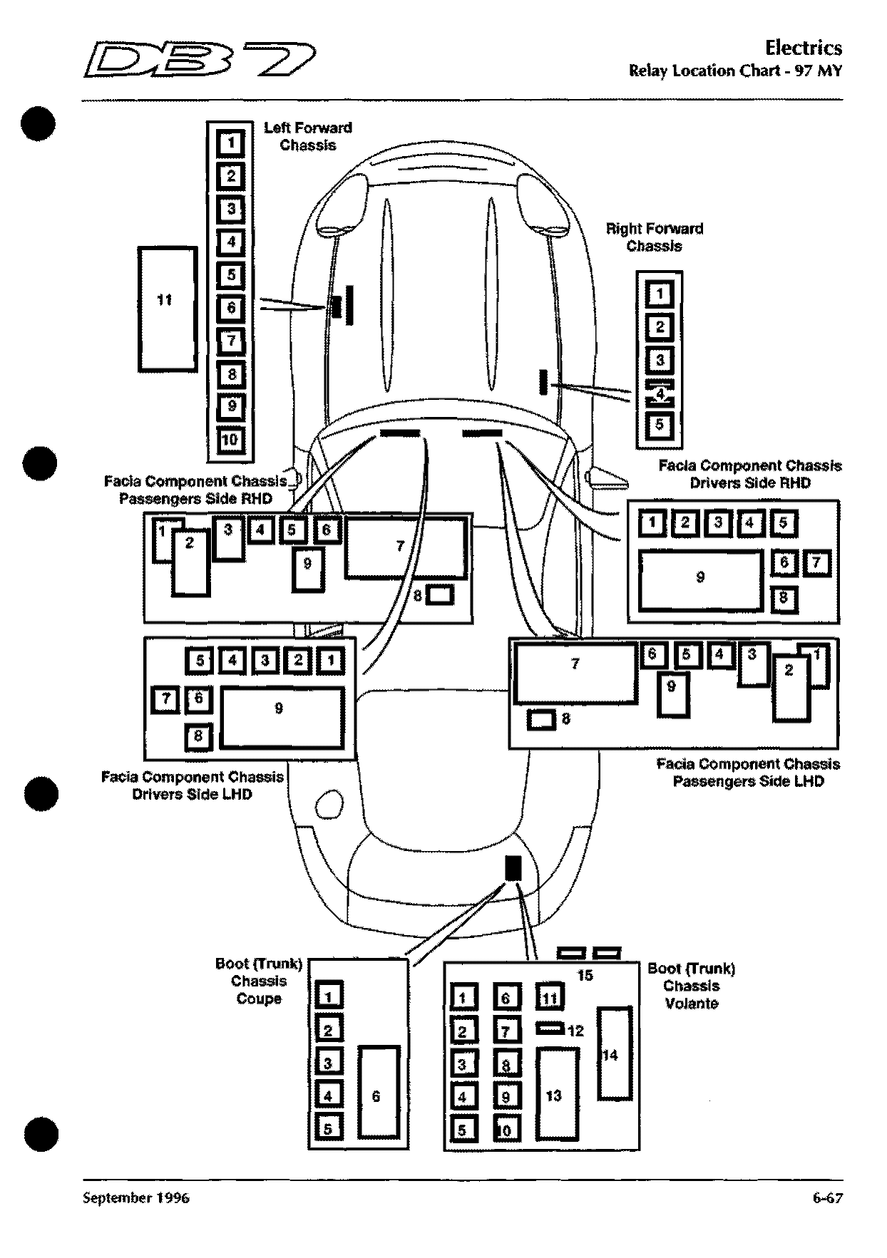
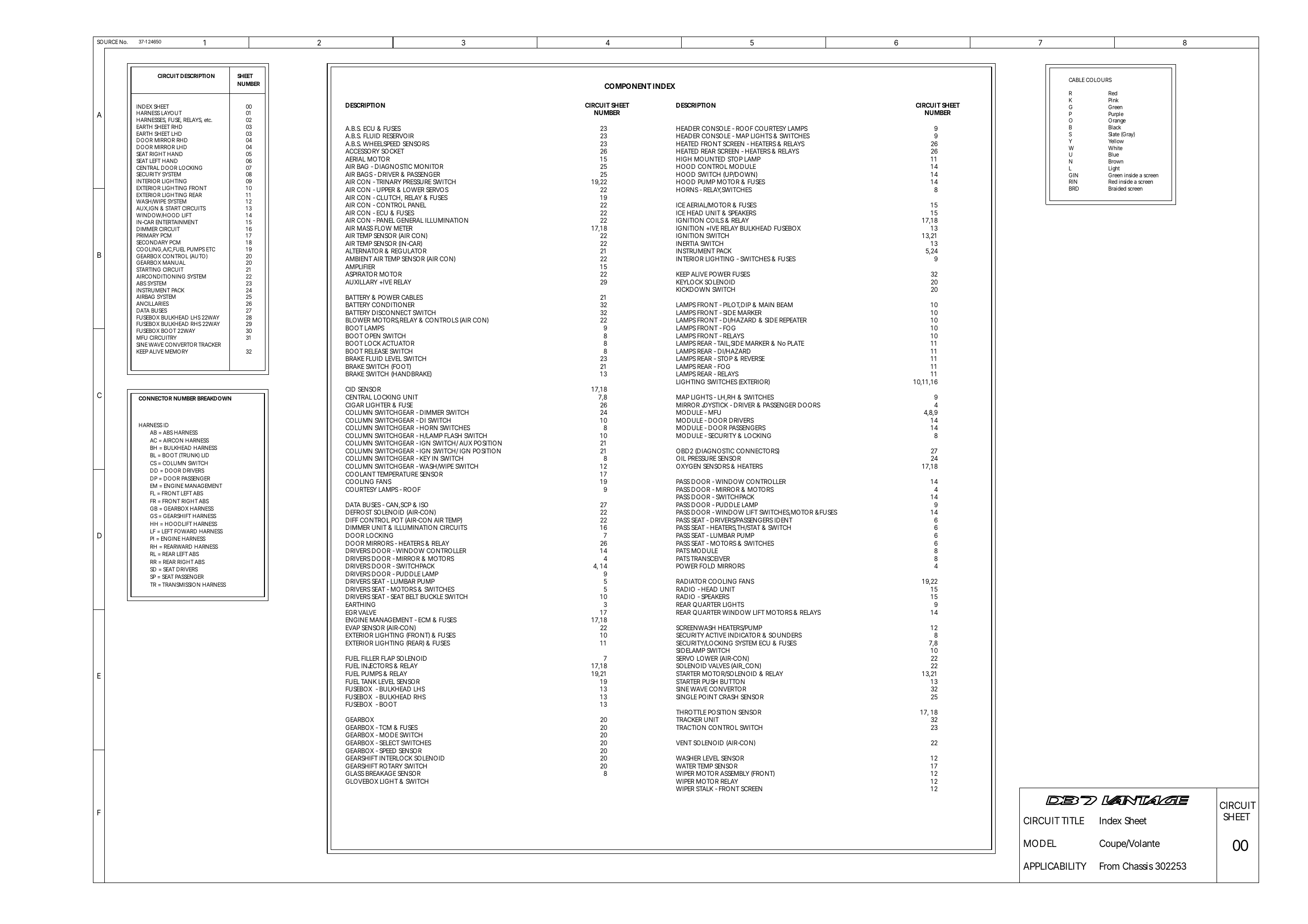
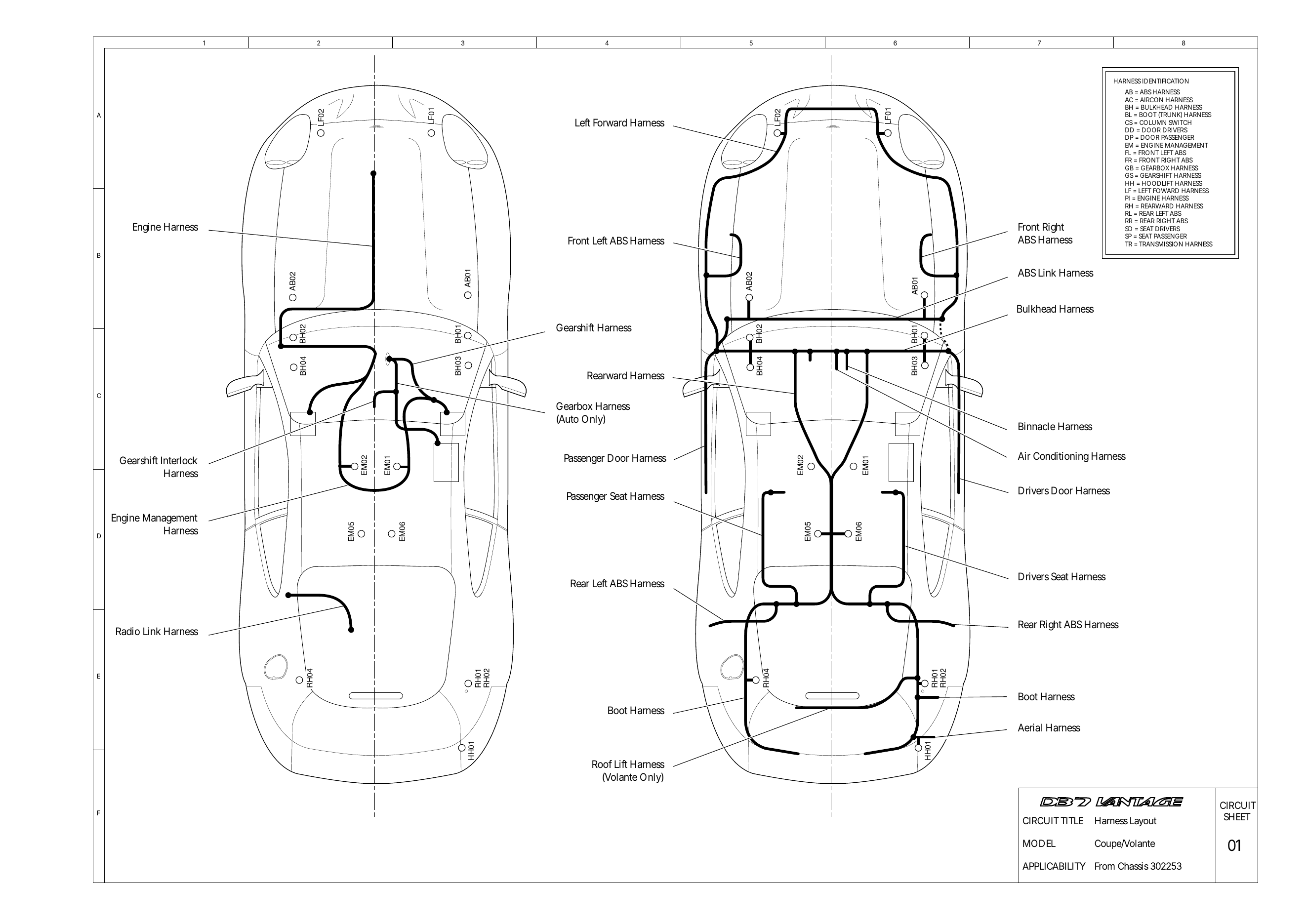
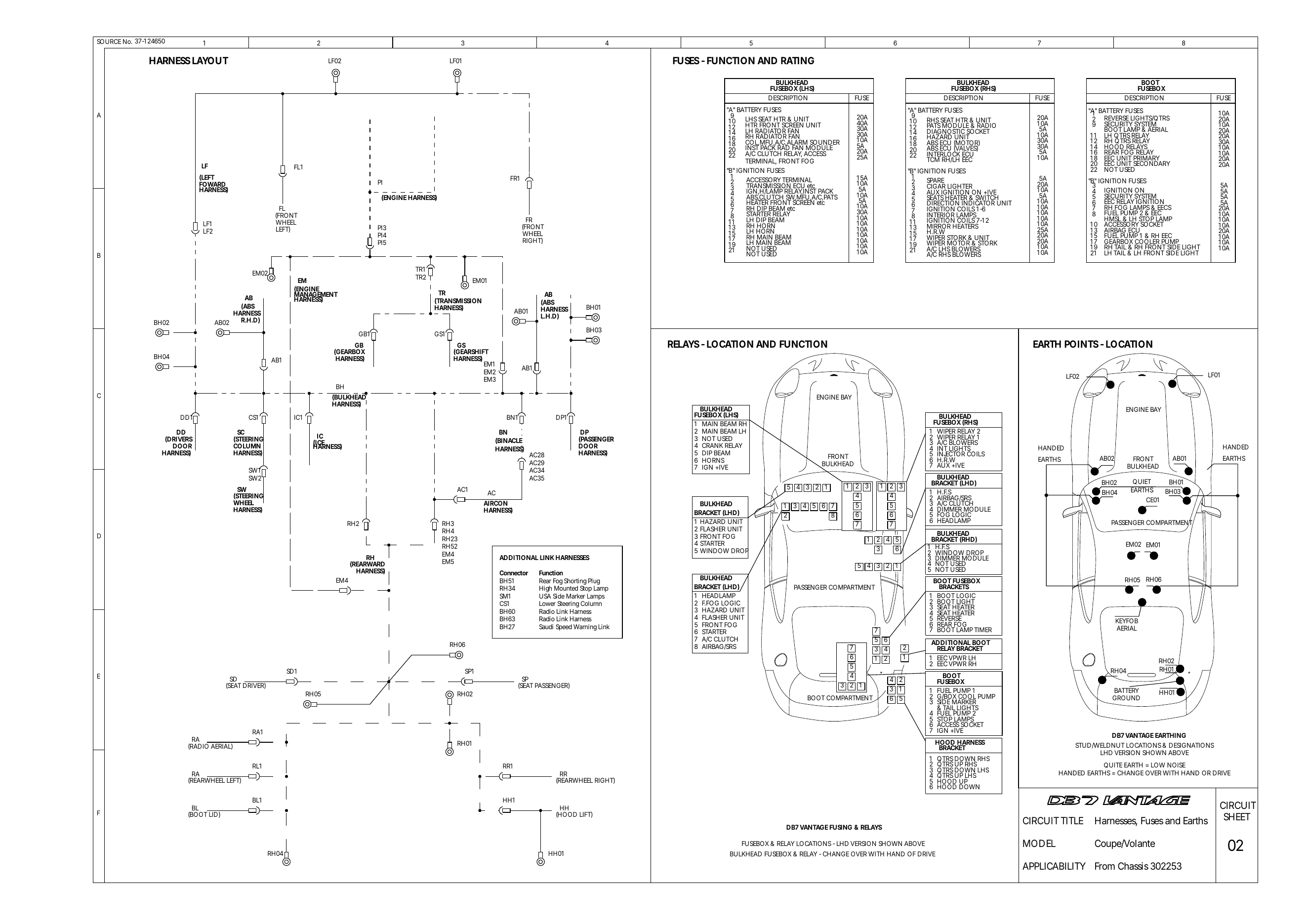
V12 Vantage circuit diagrams
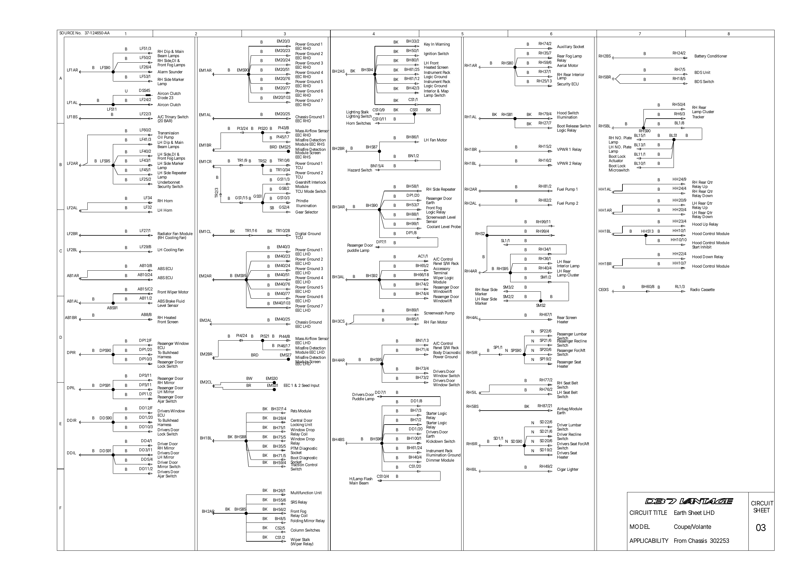
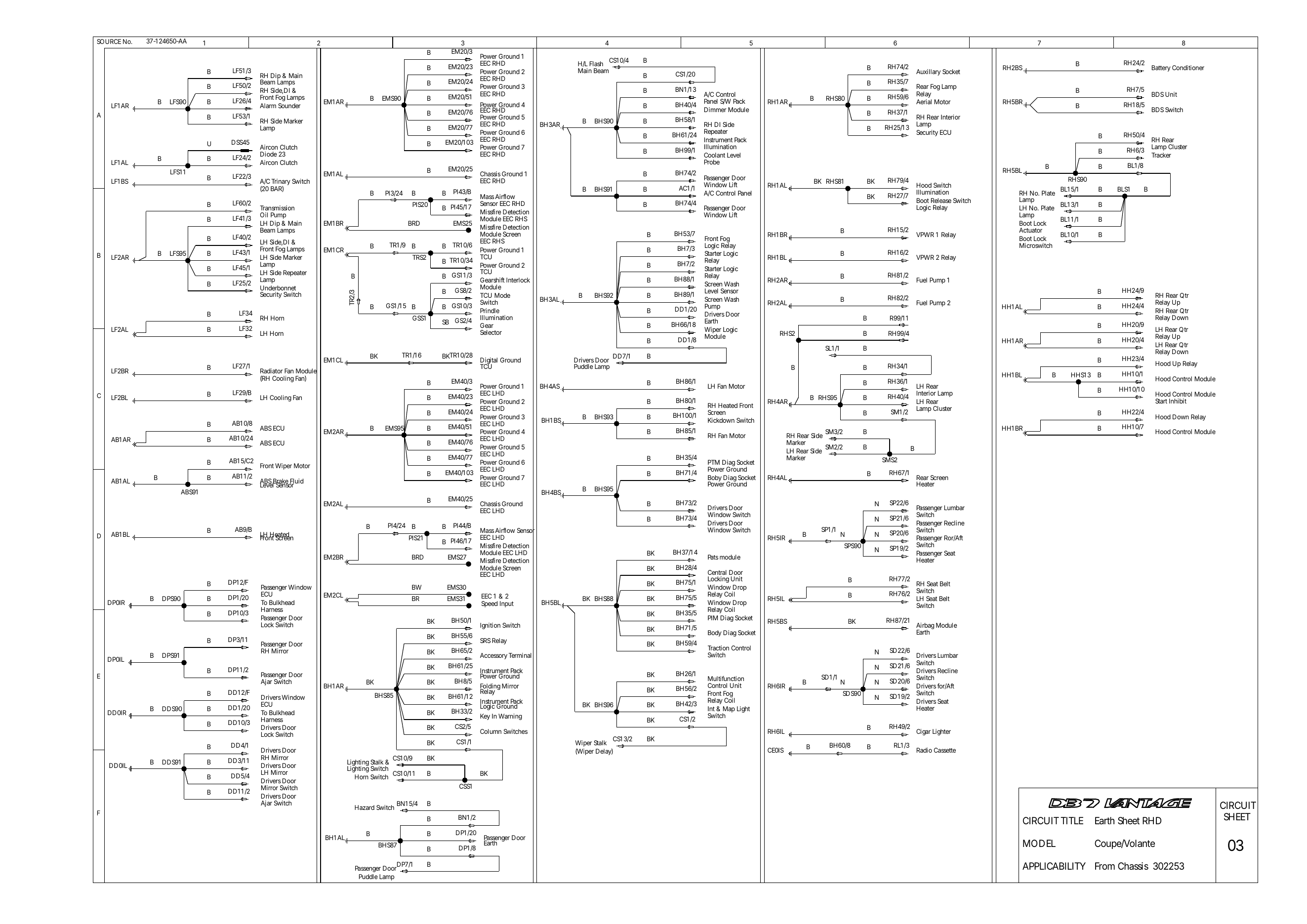
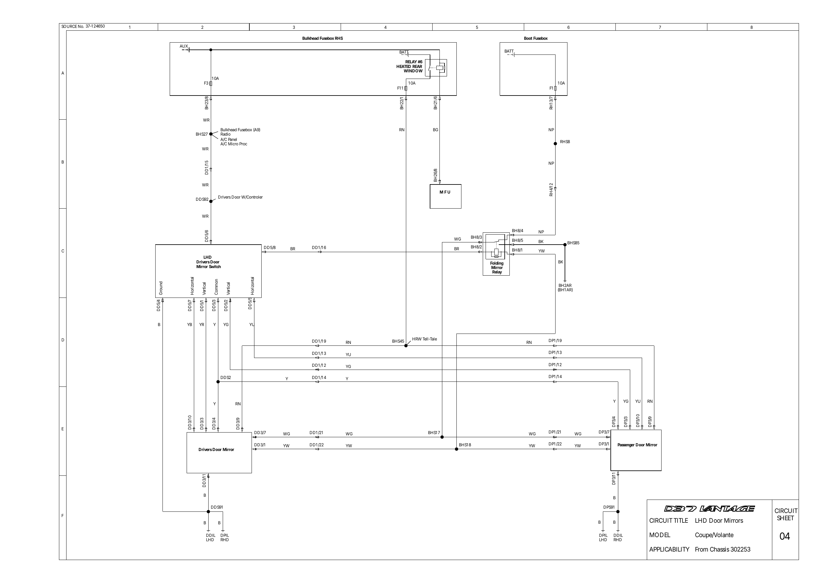
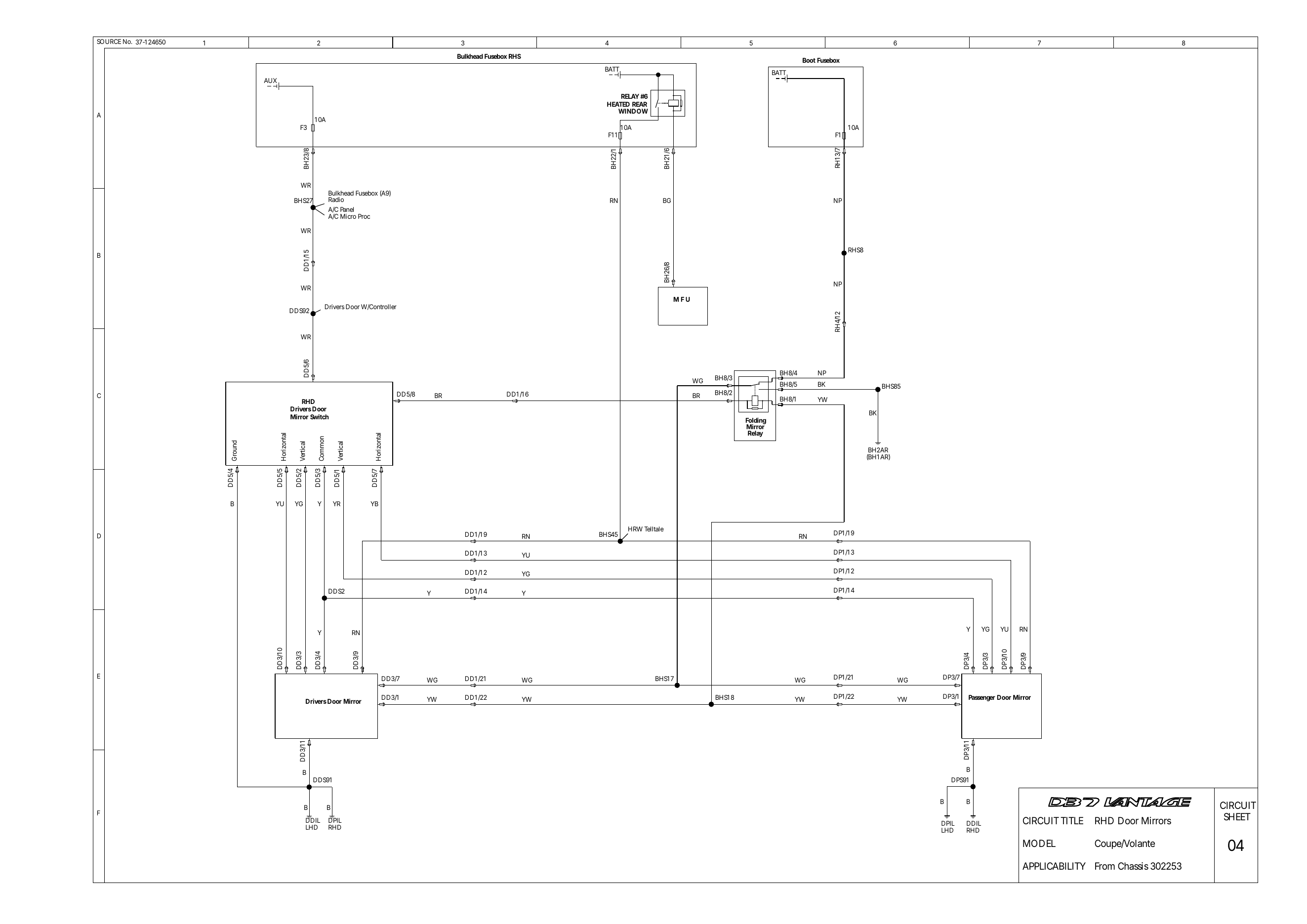
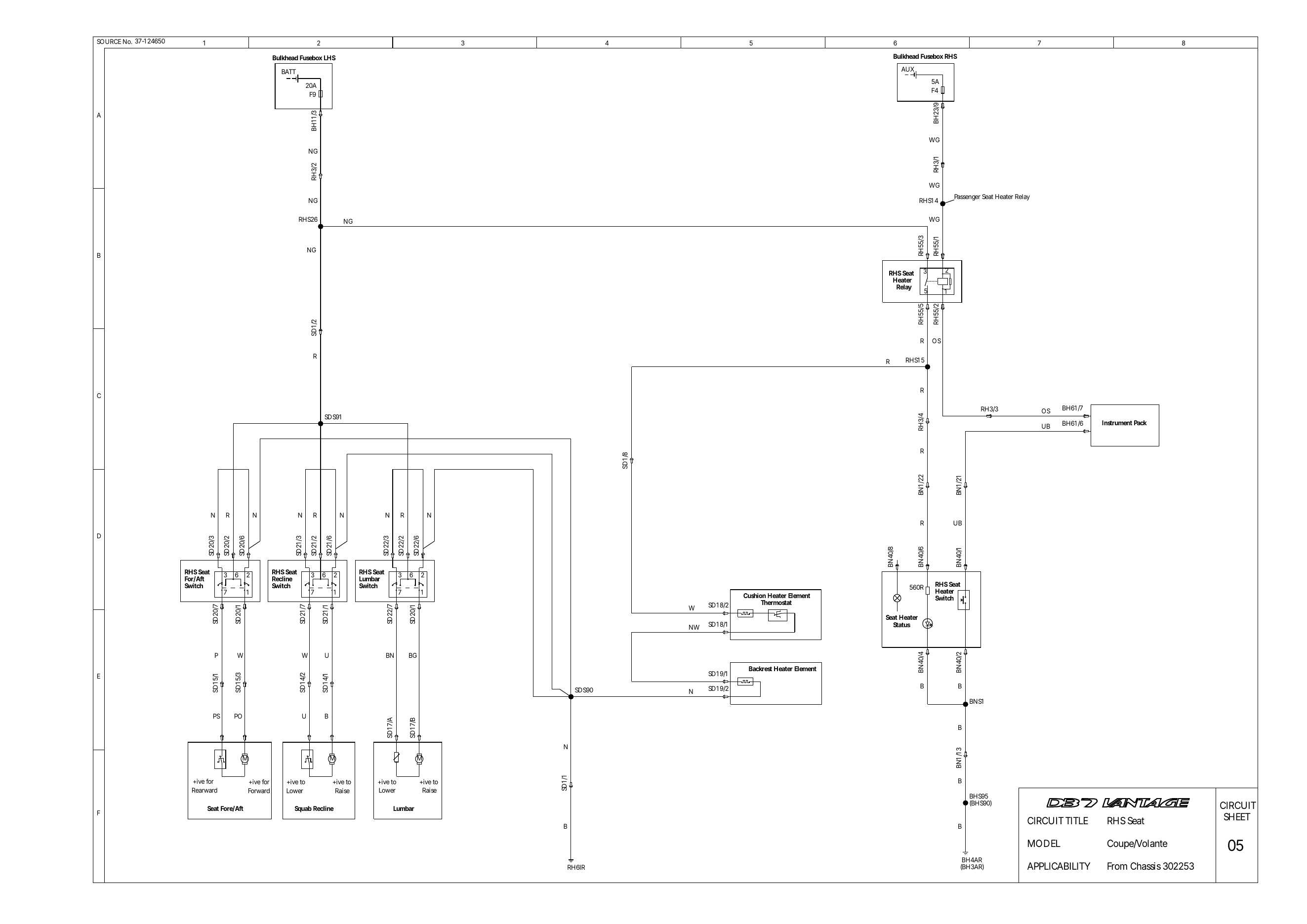
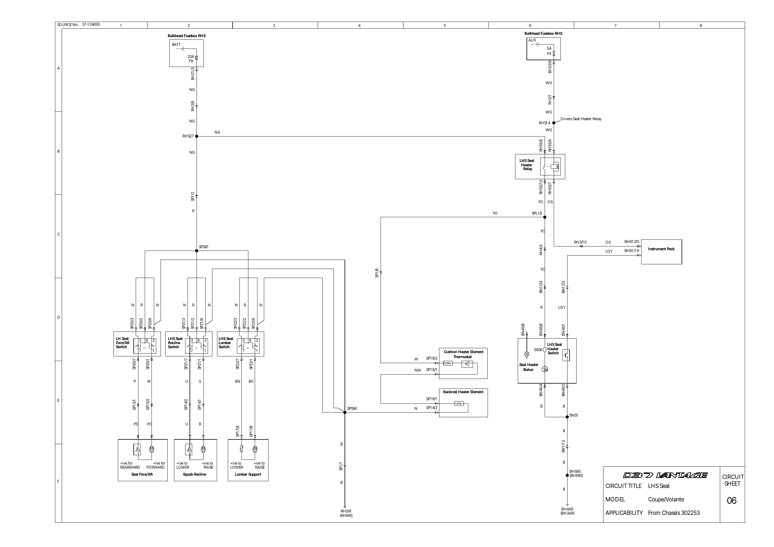
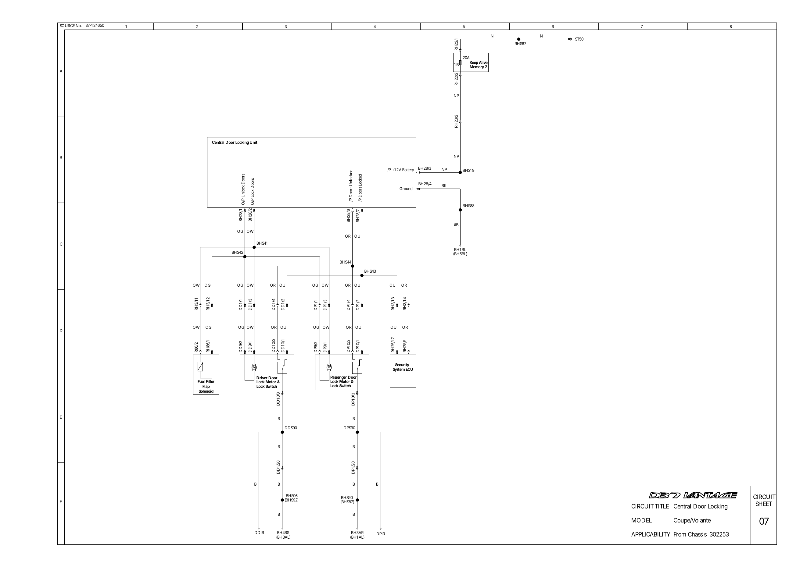
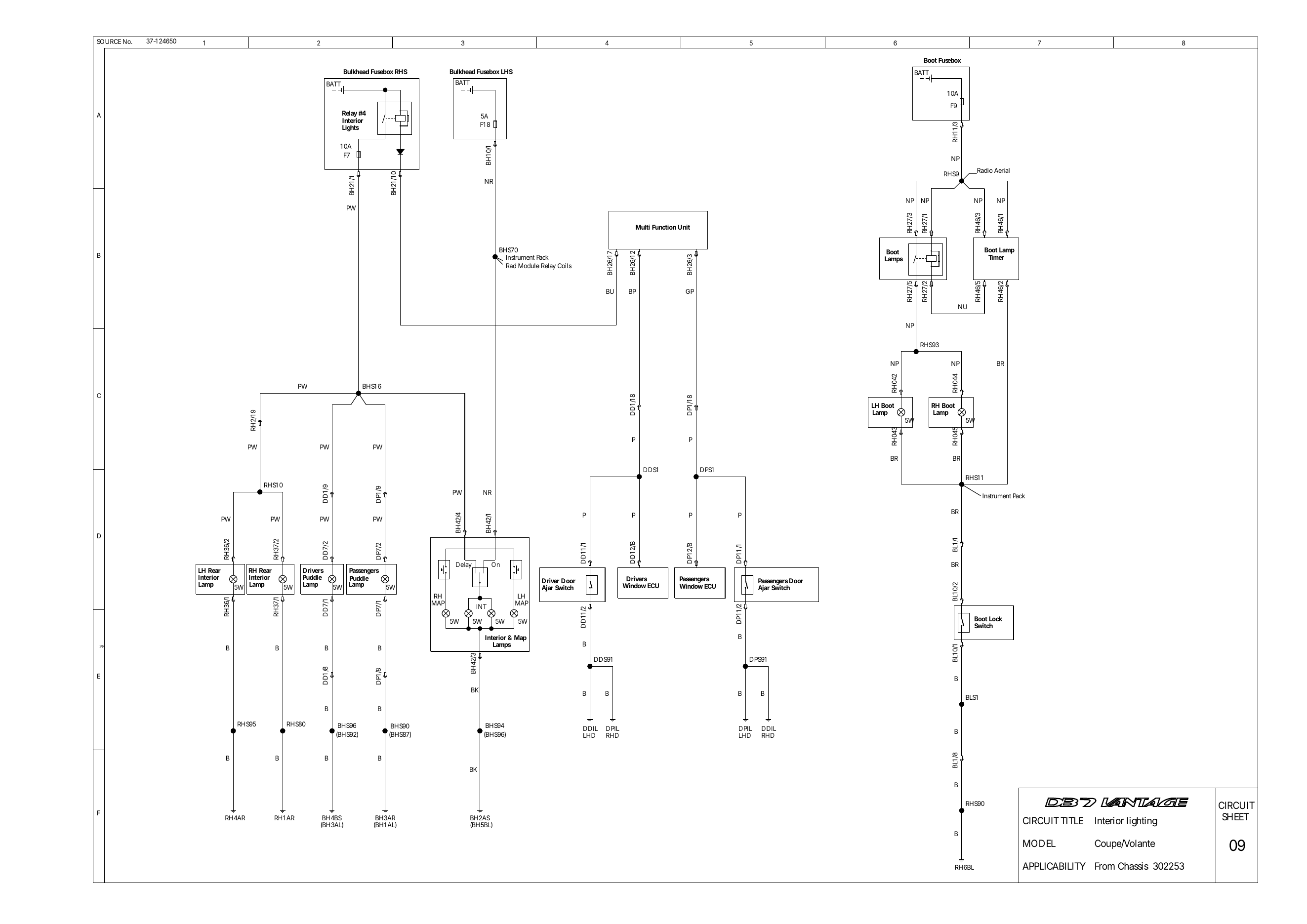
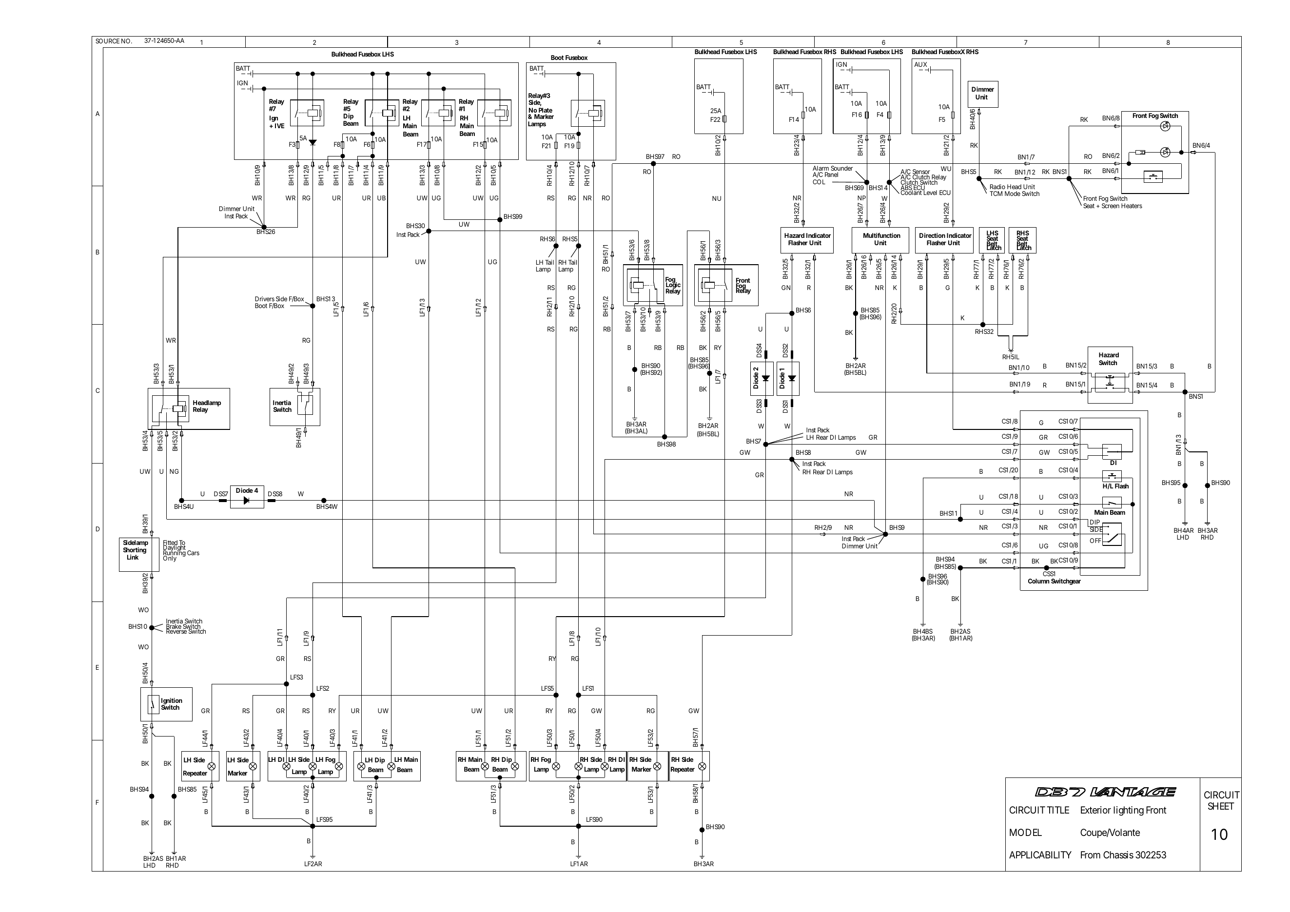
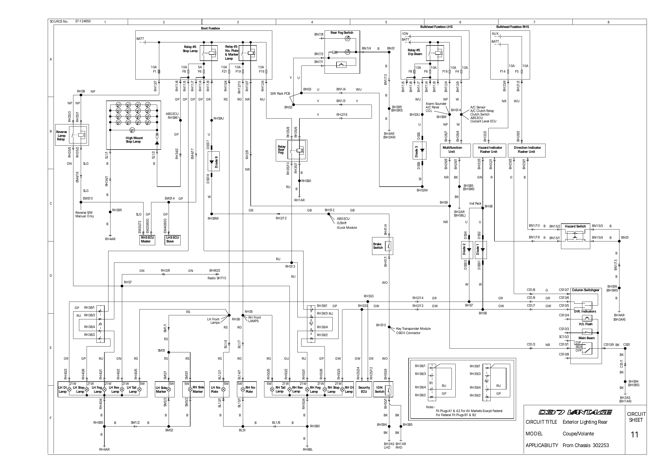
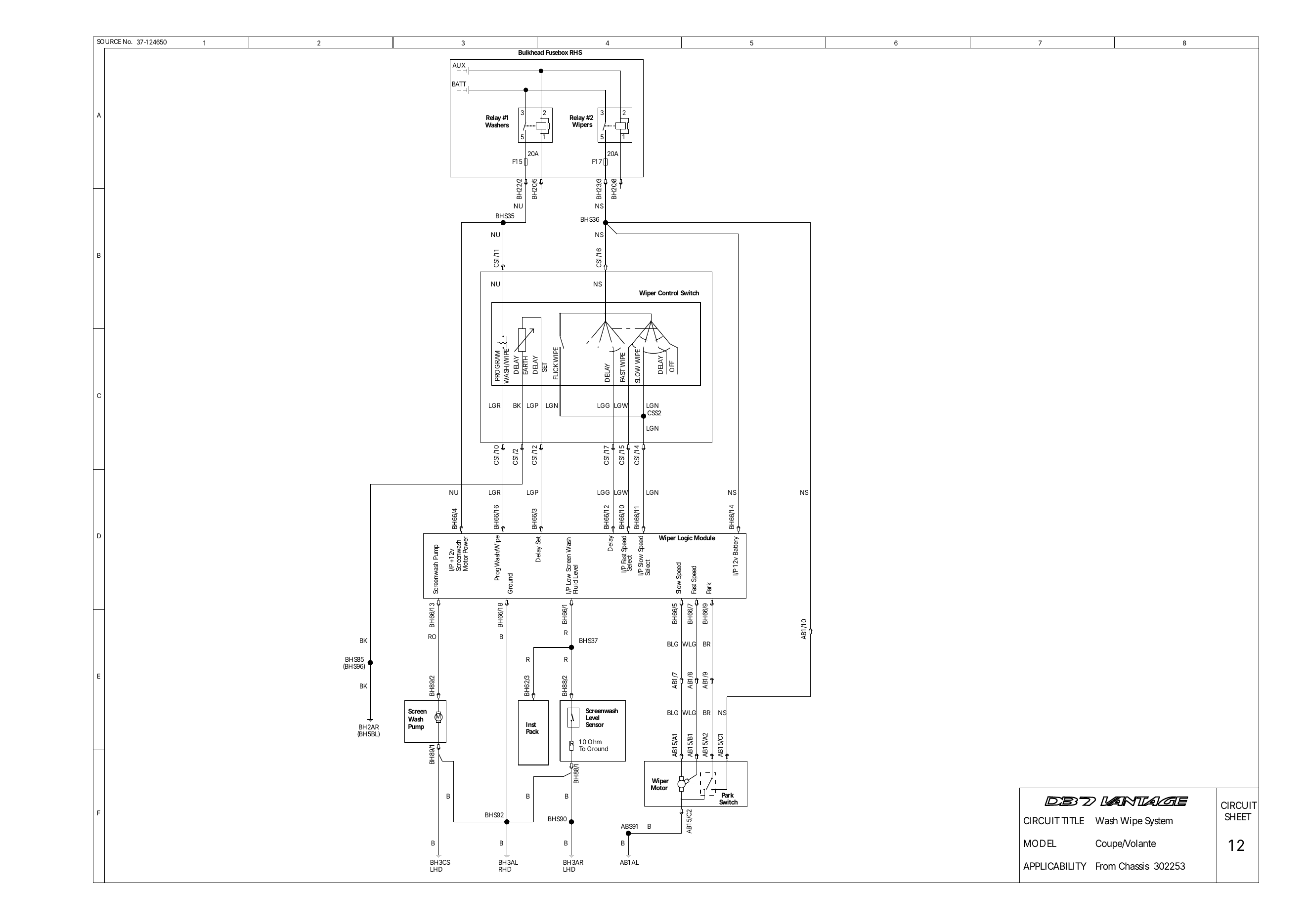
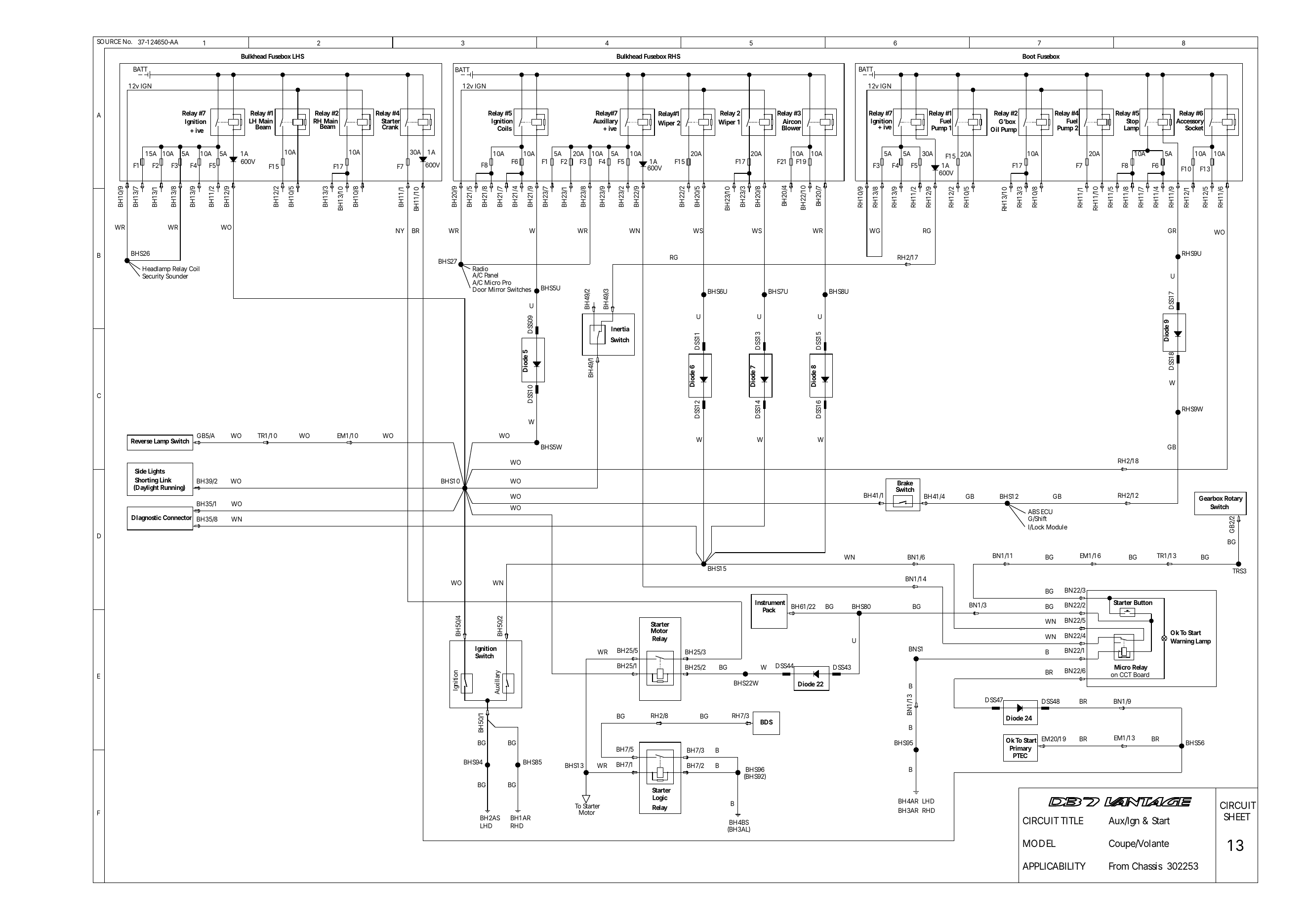
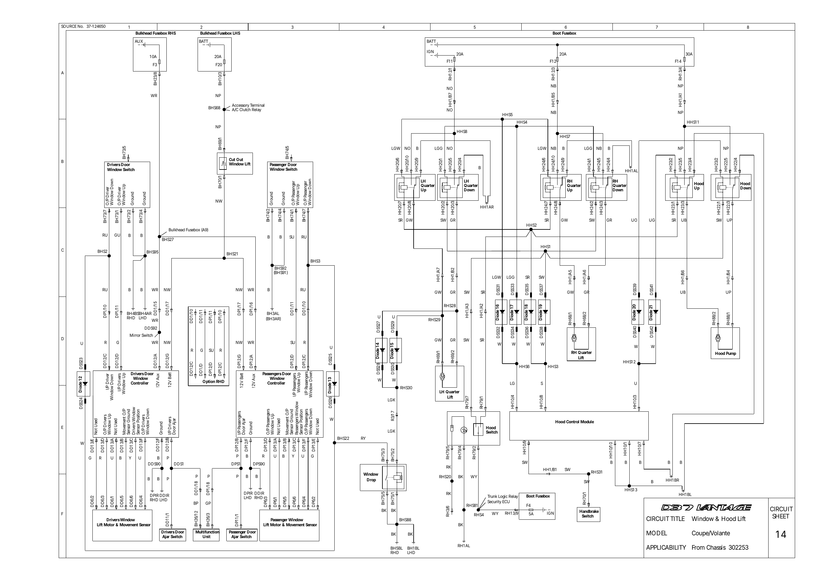
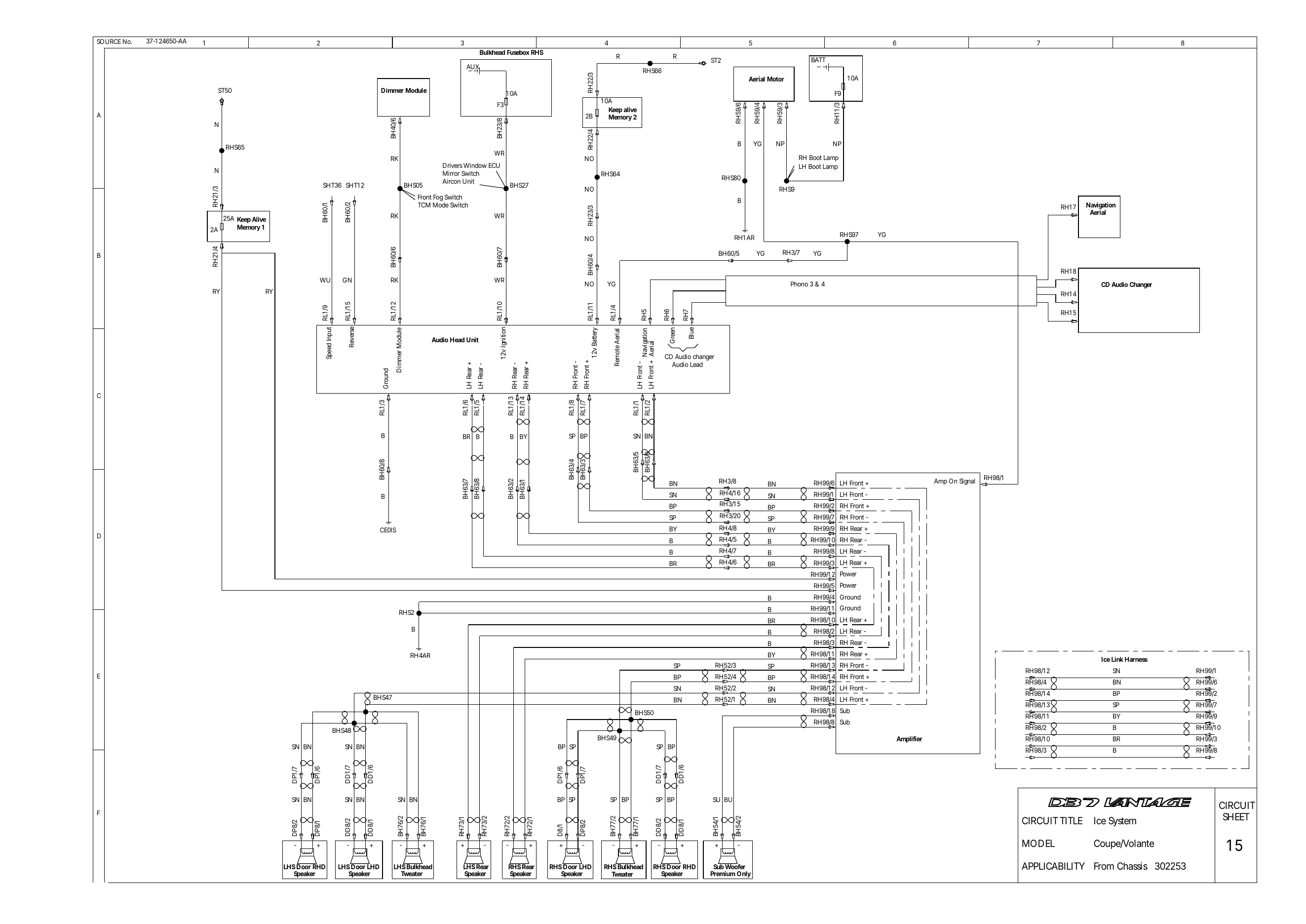
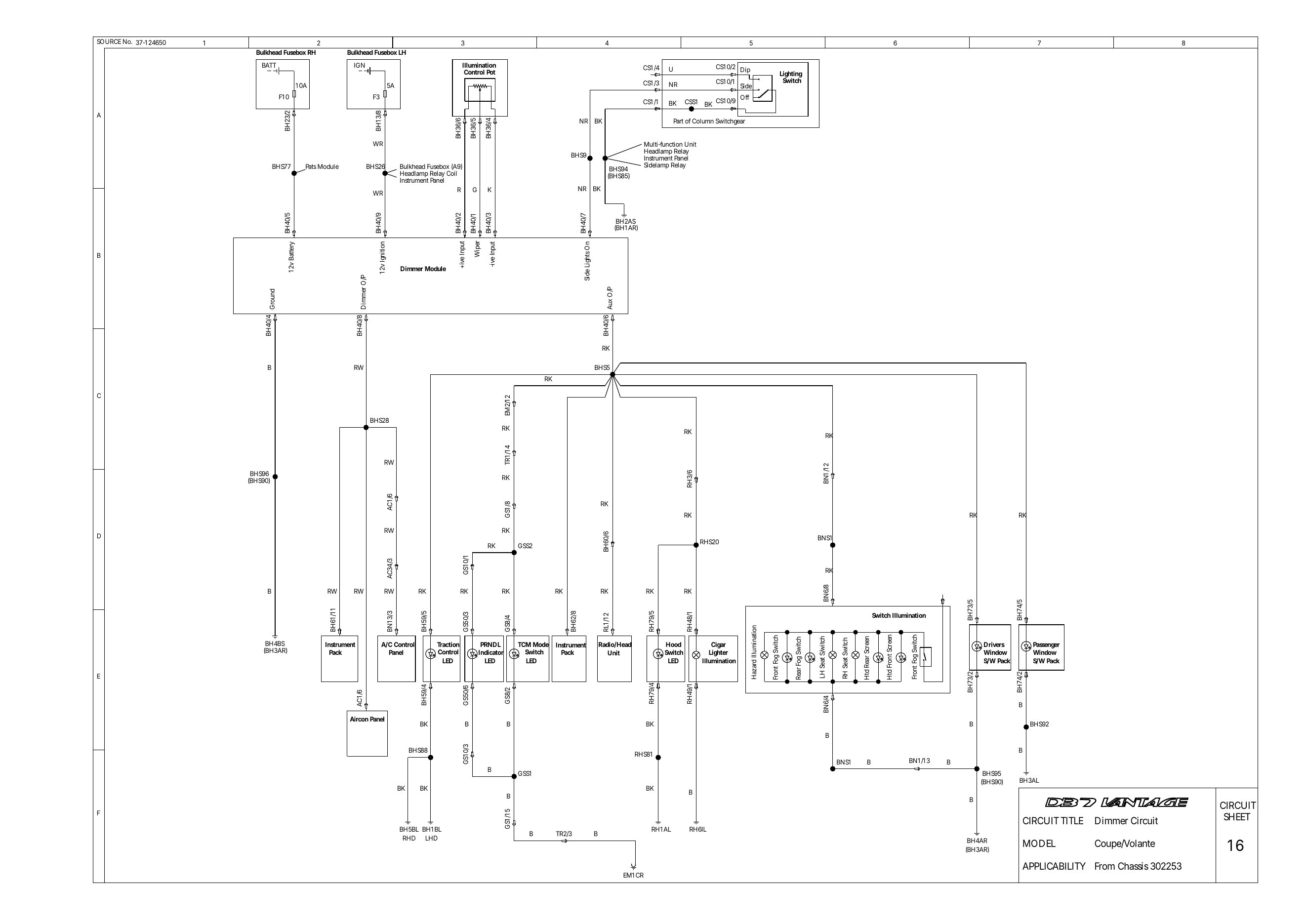
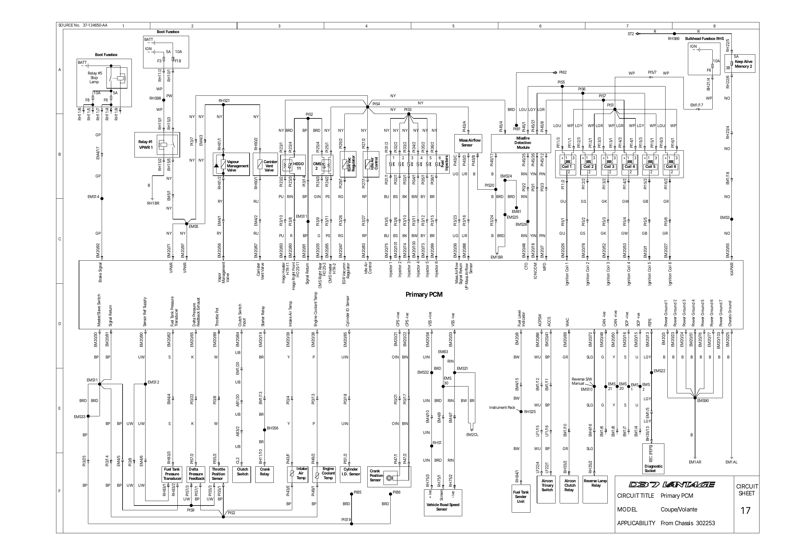
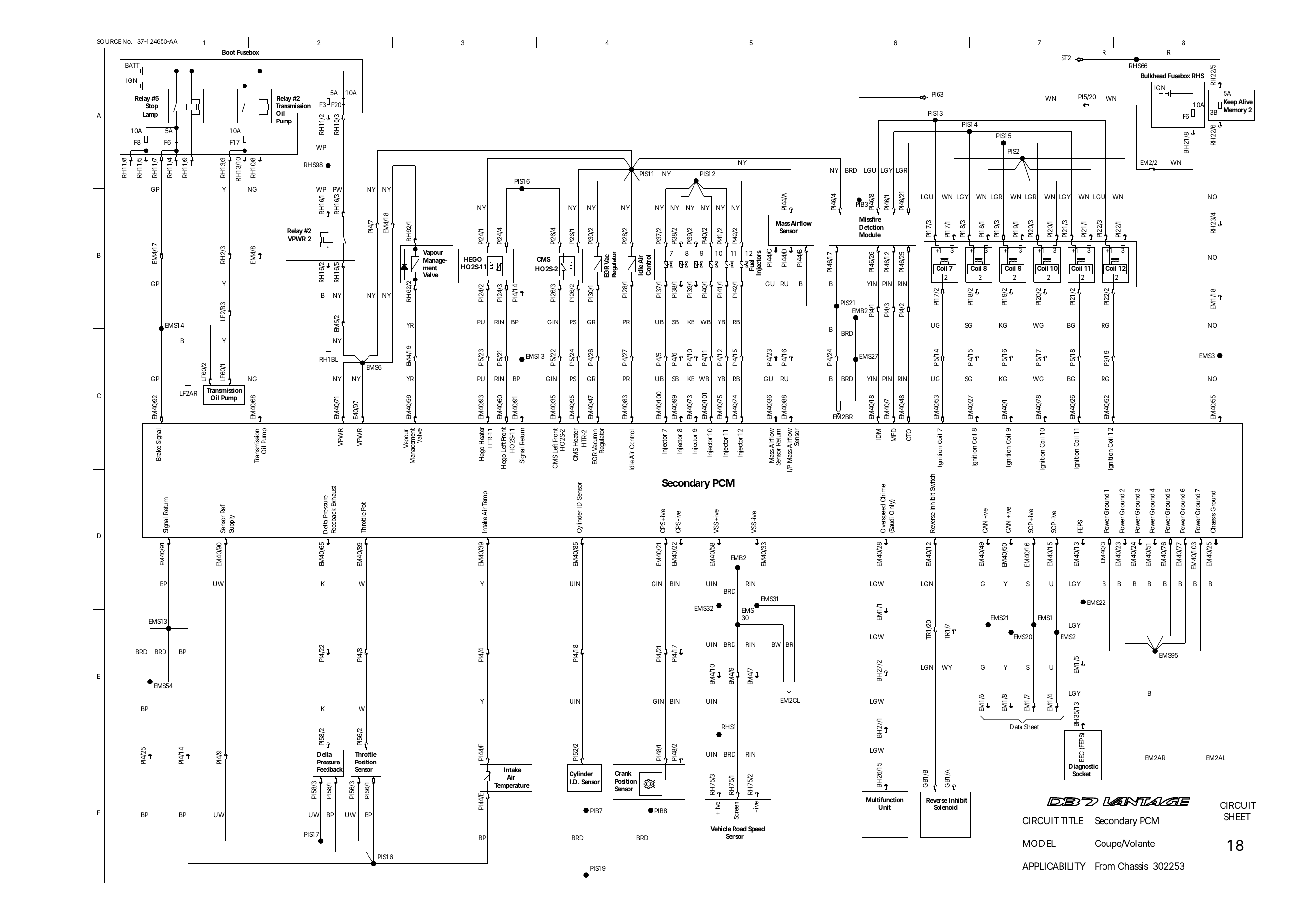
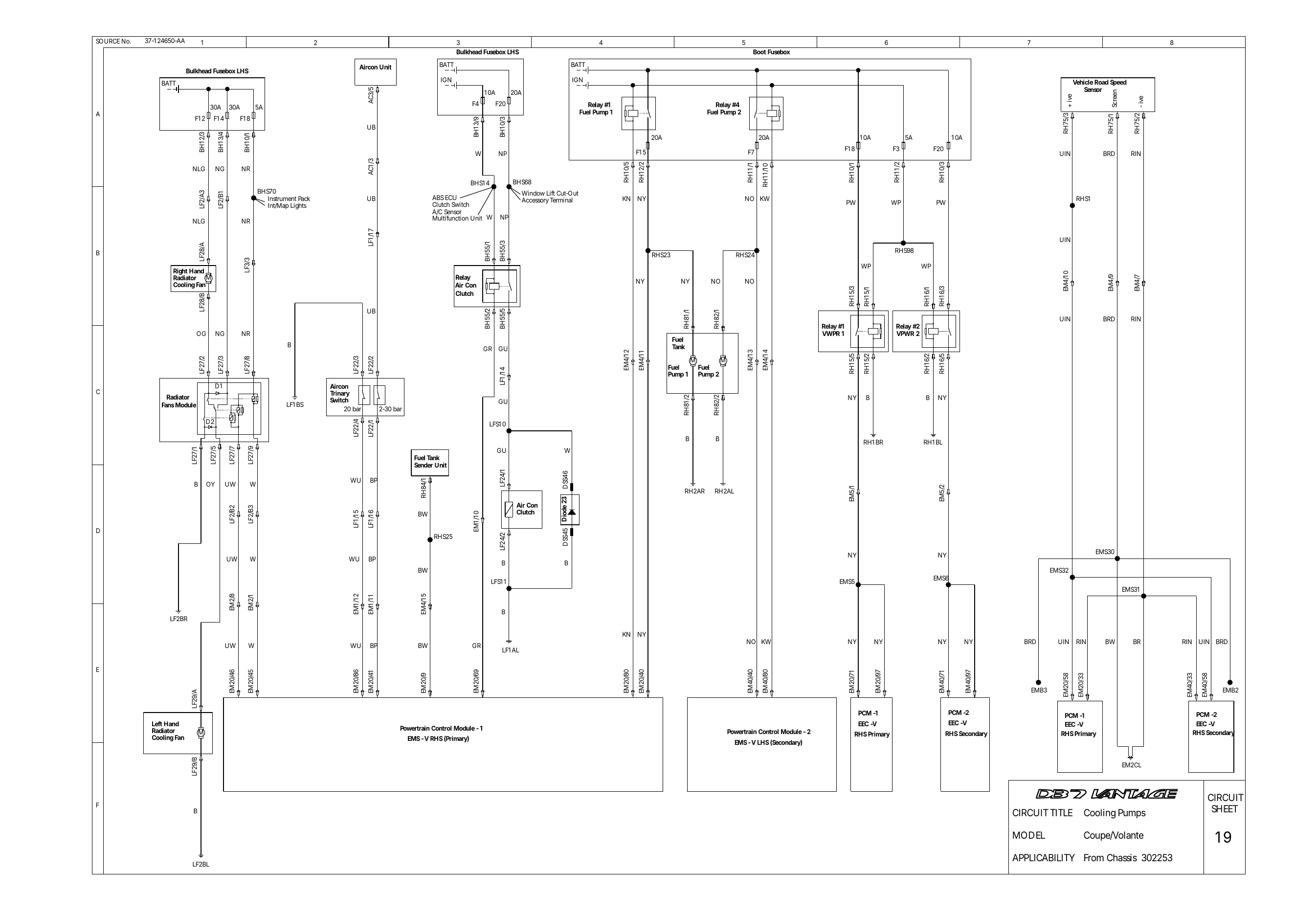
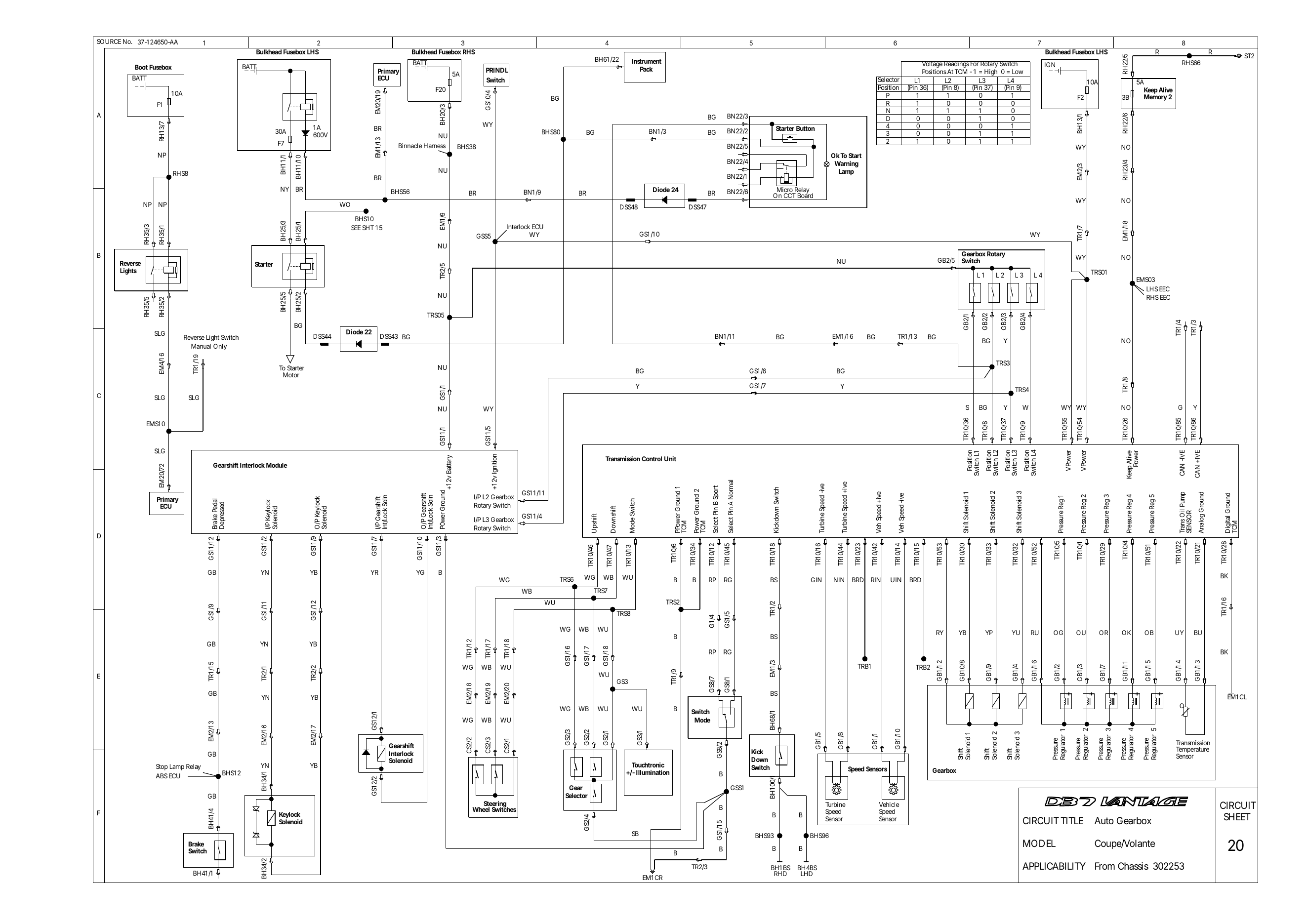
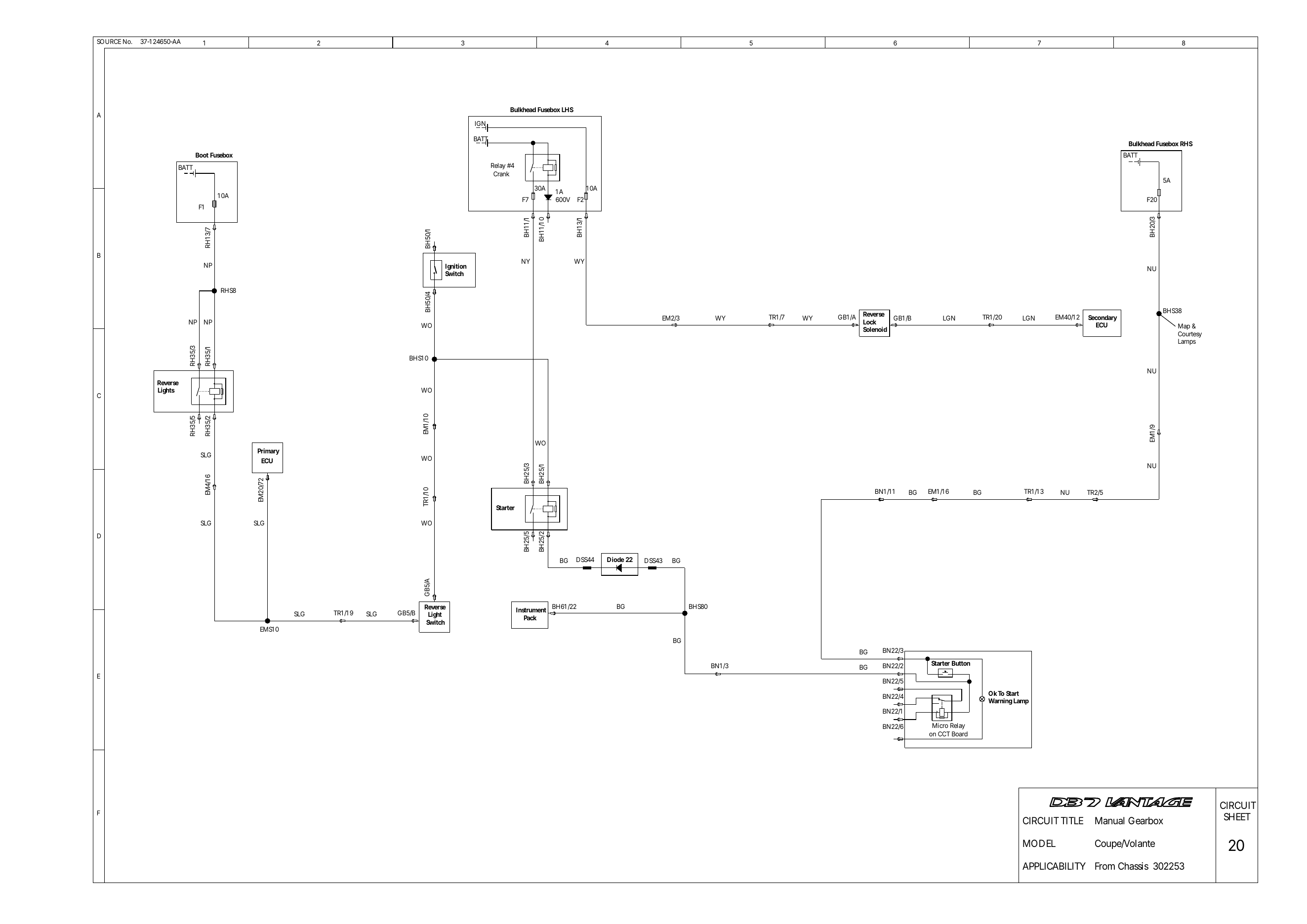
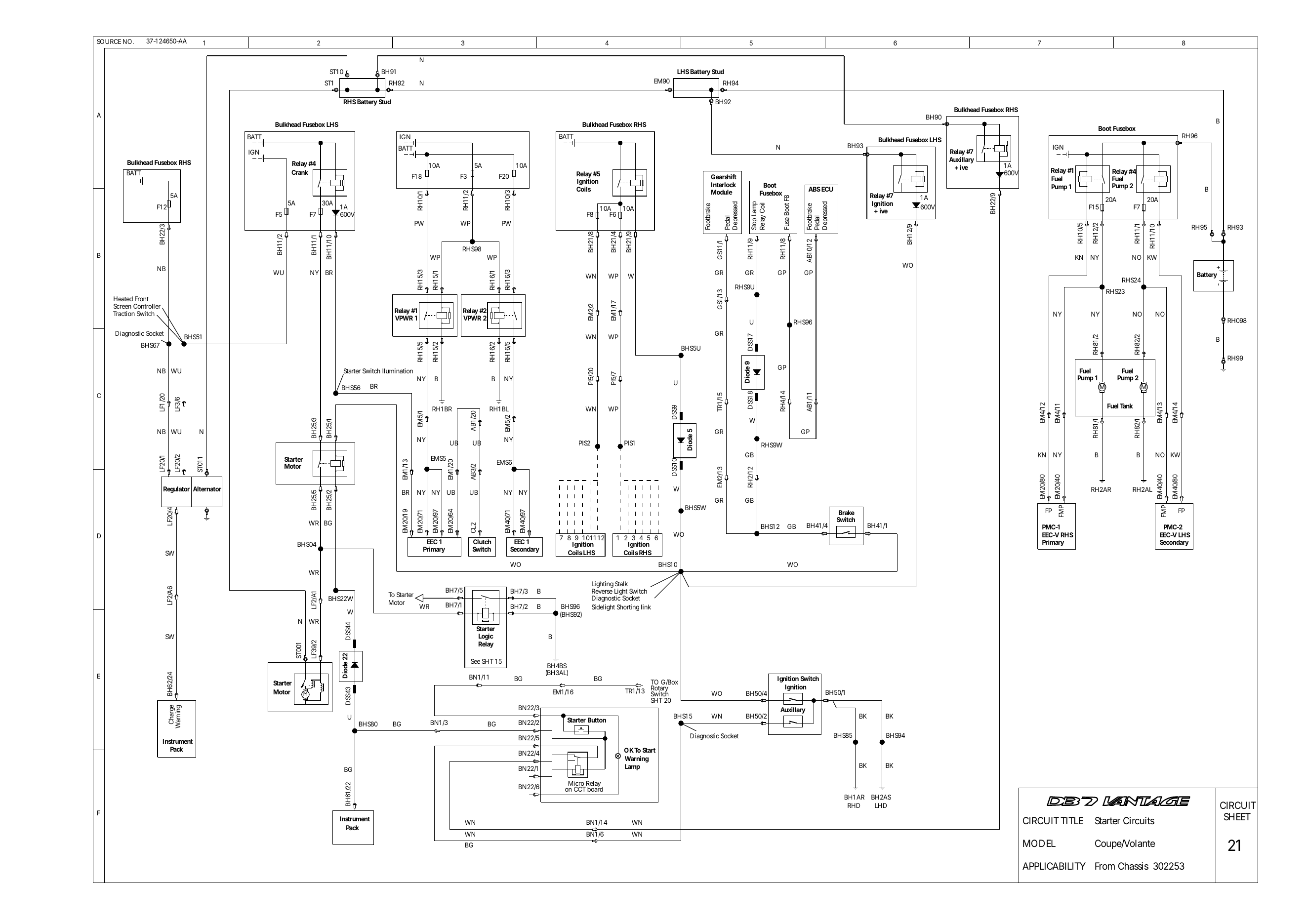
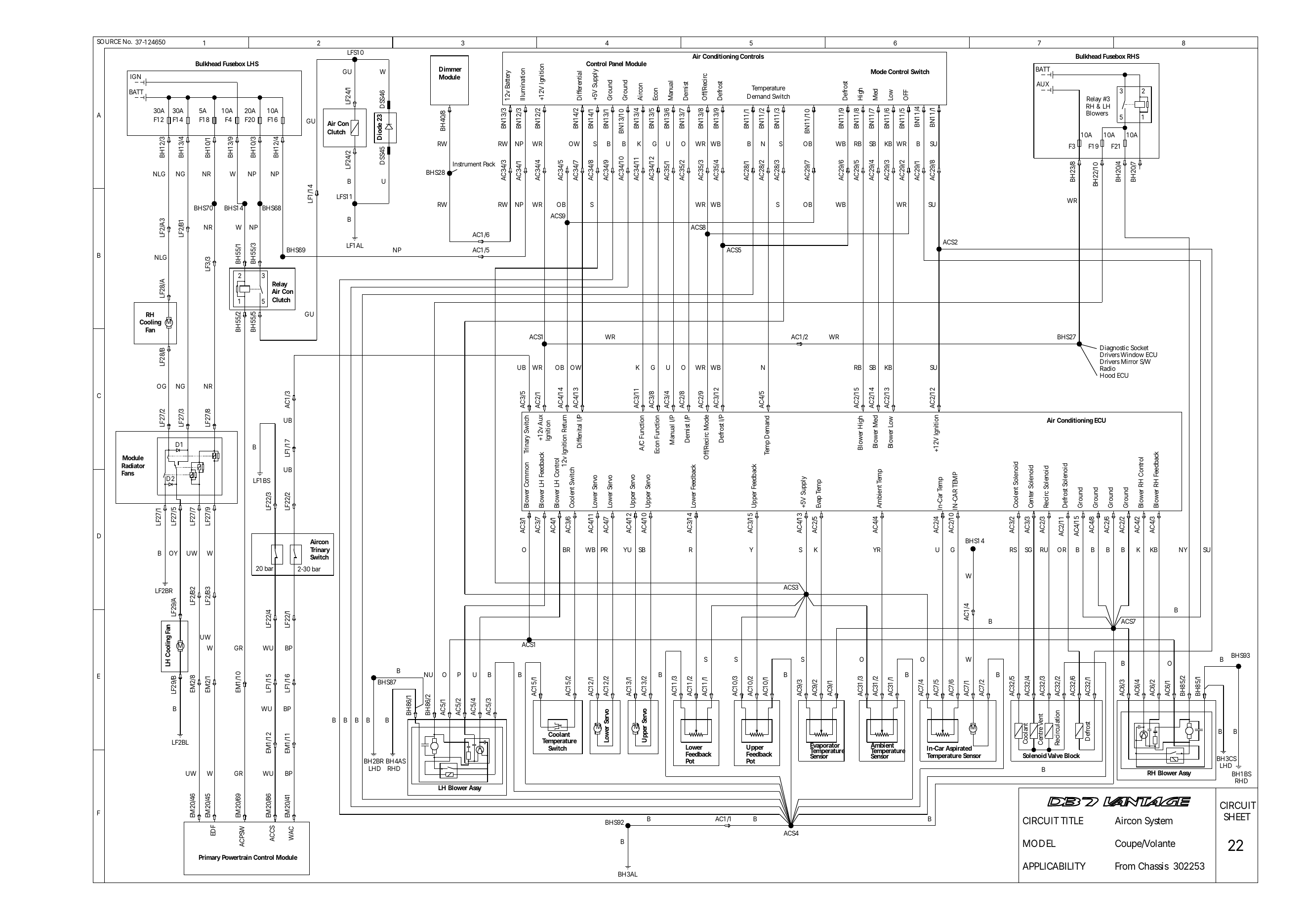
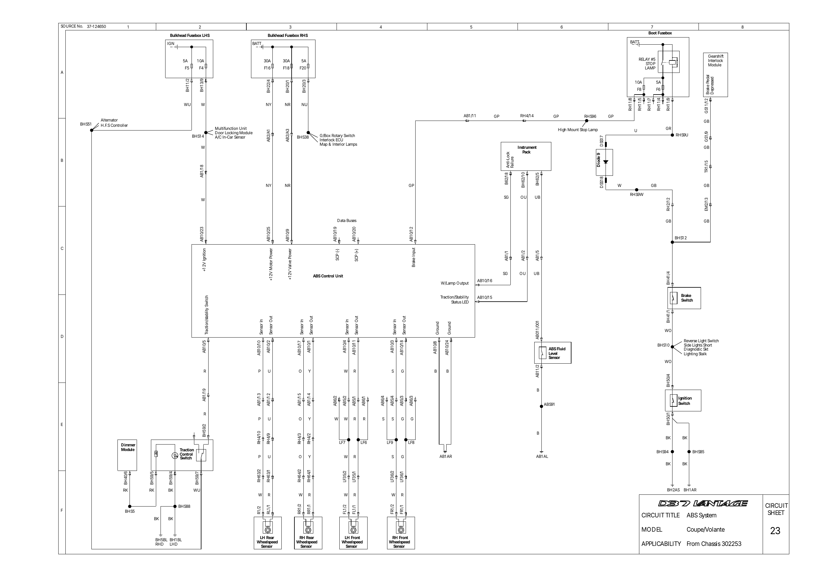
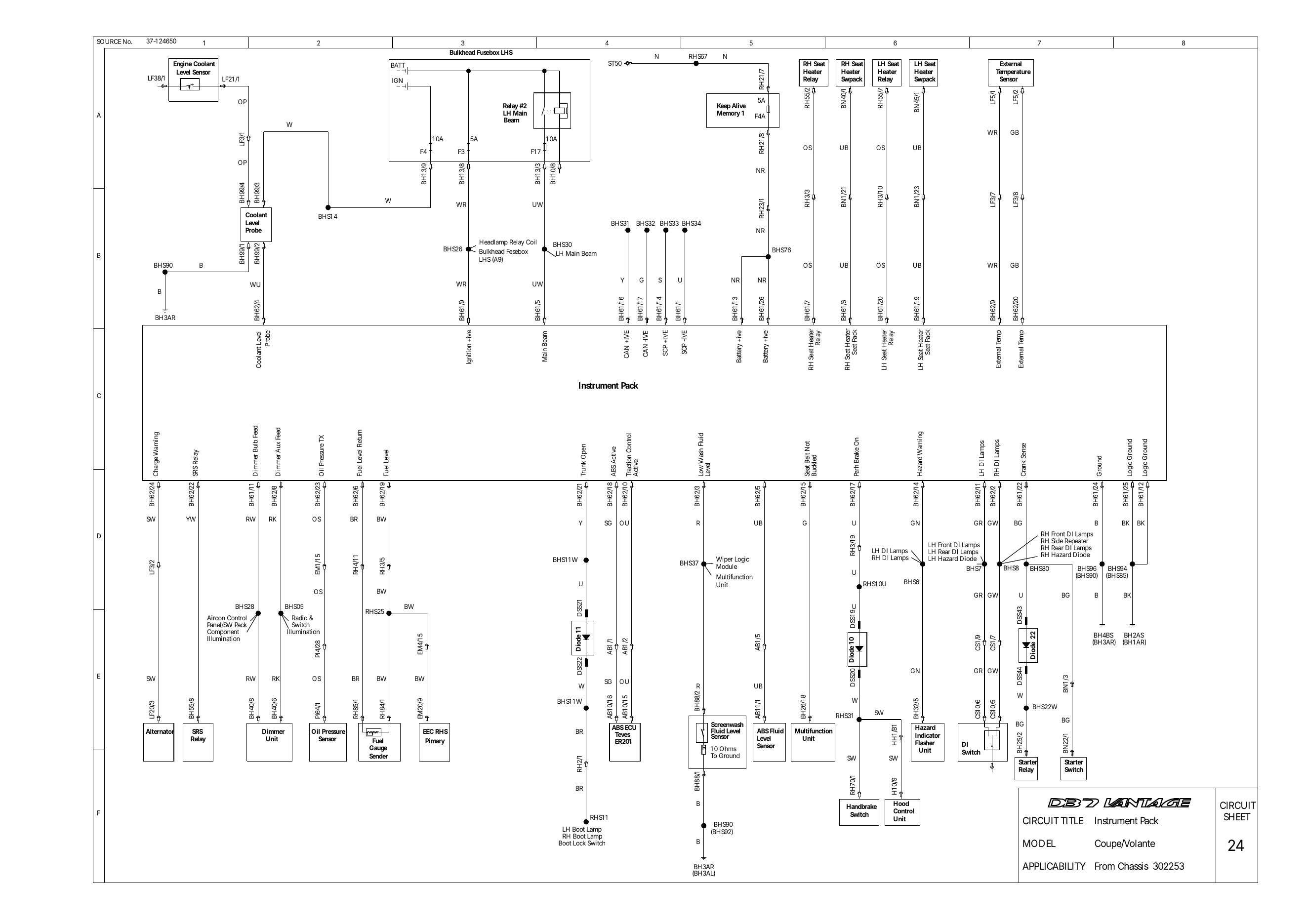
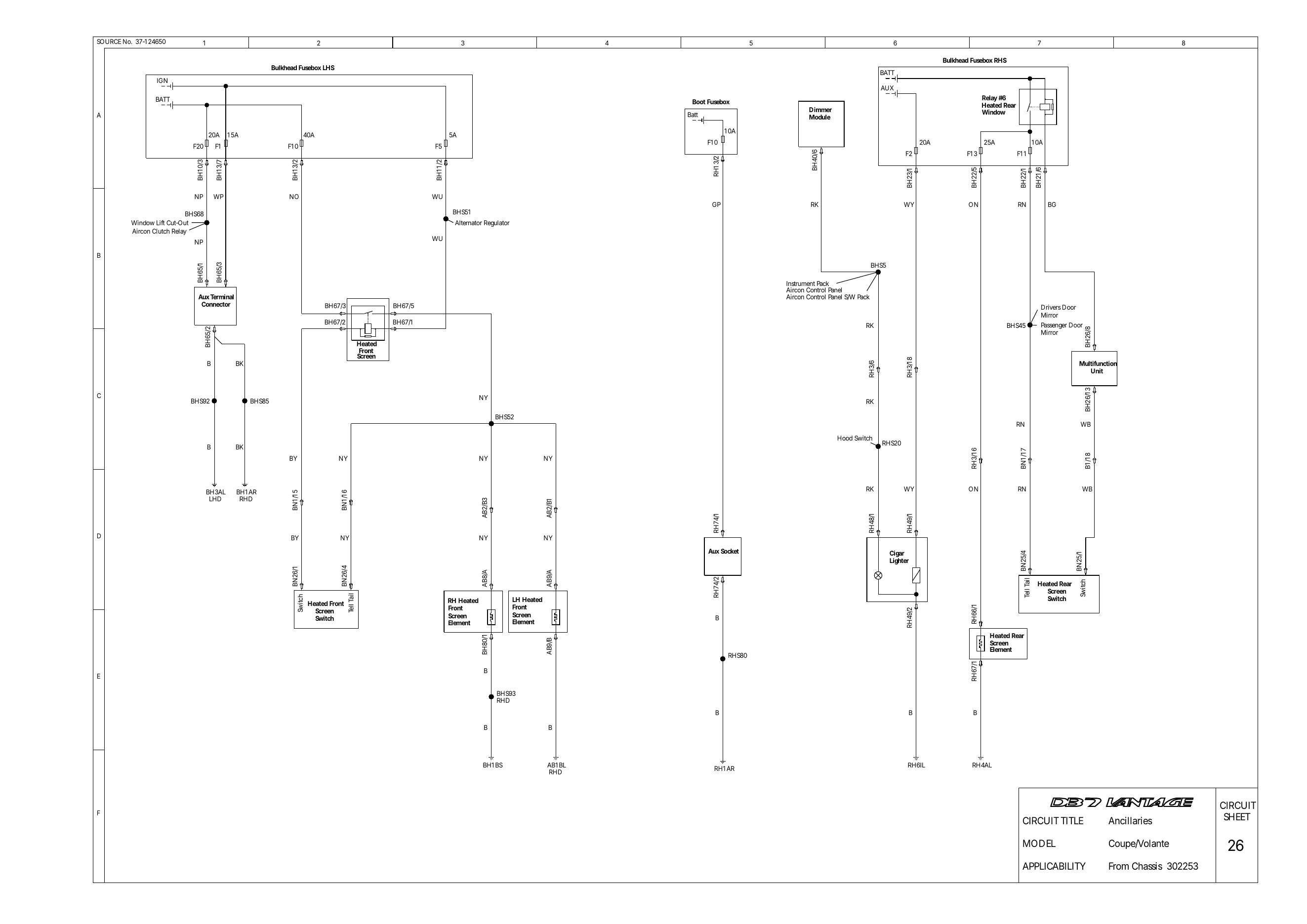
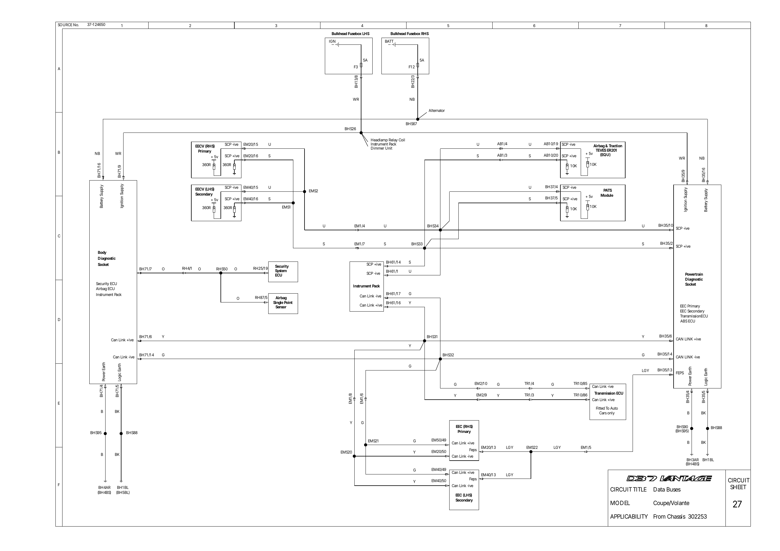
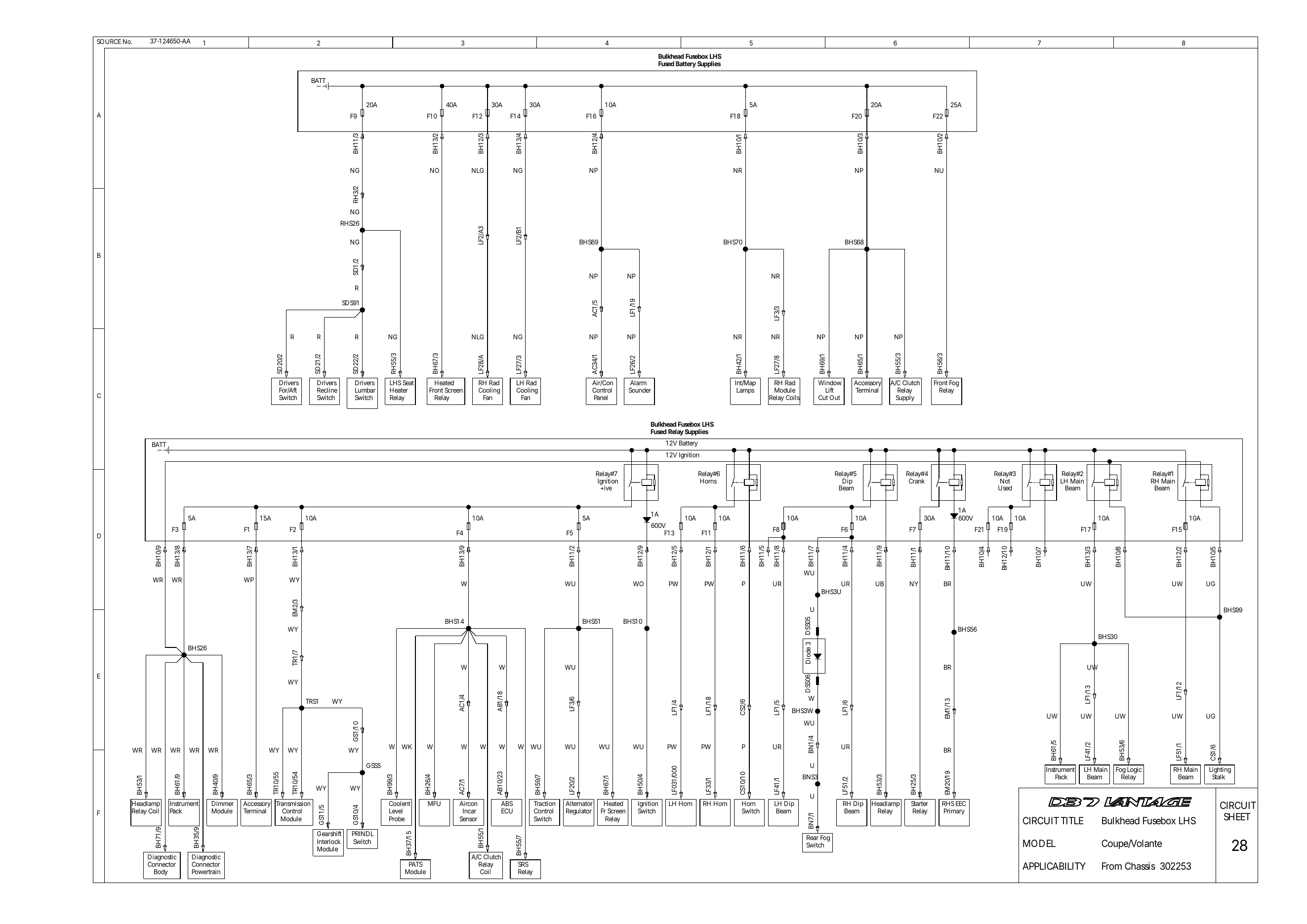
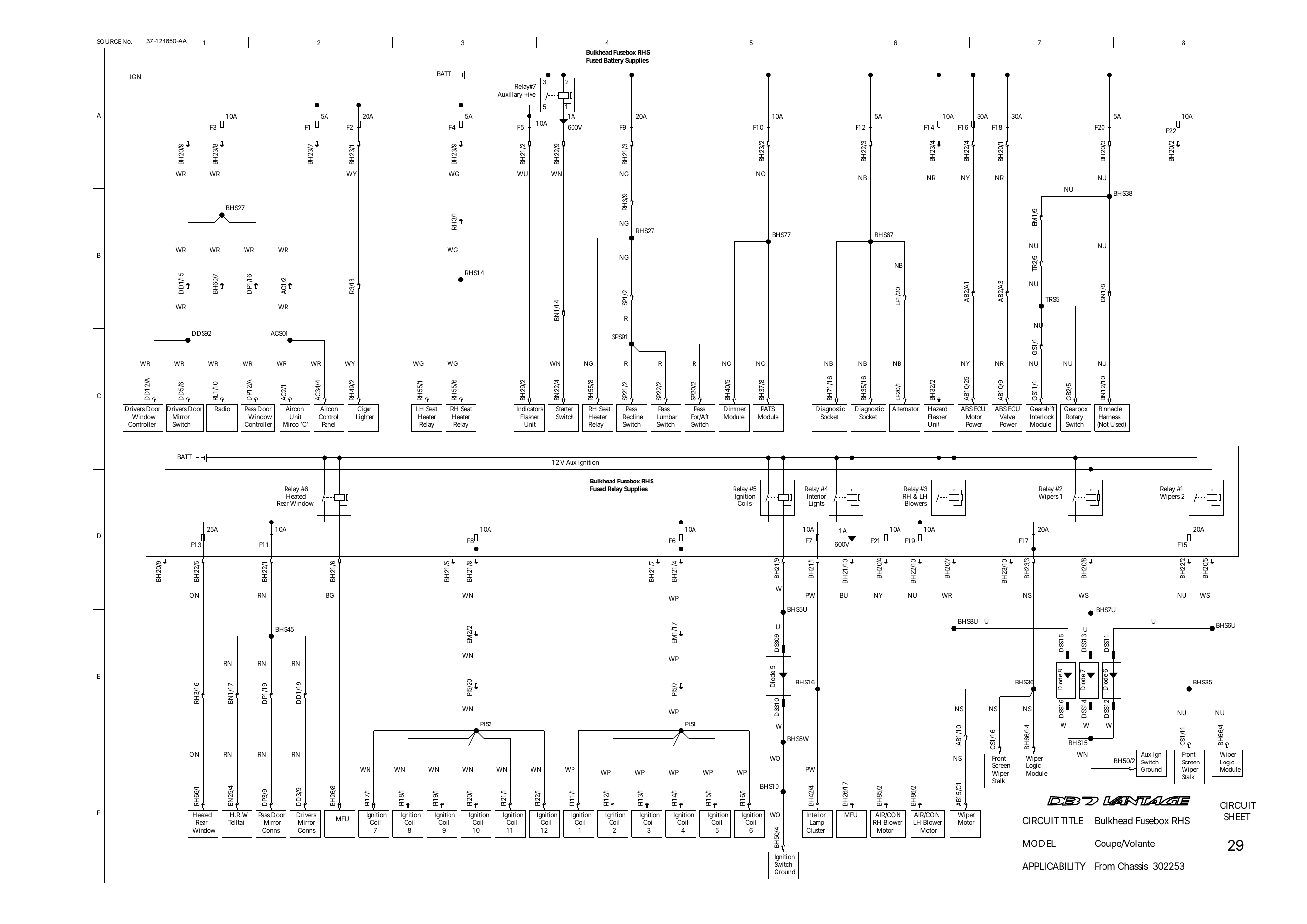
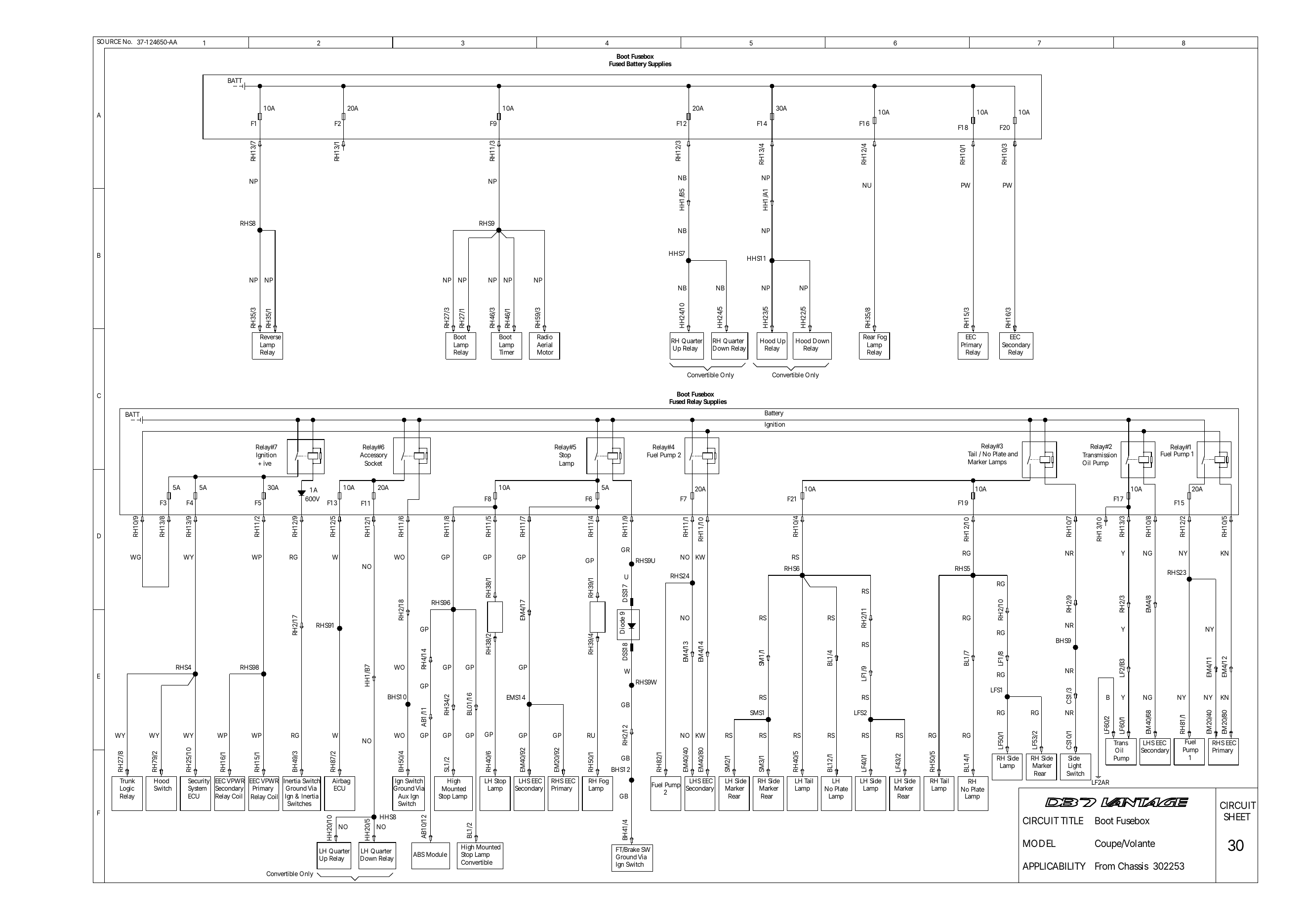
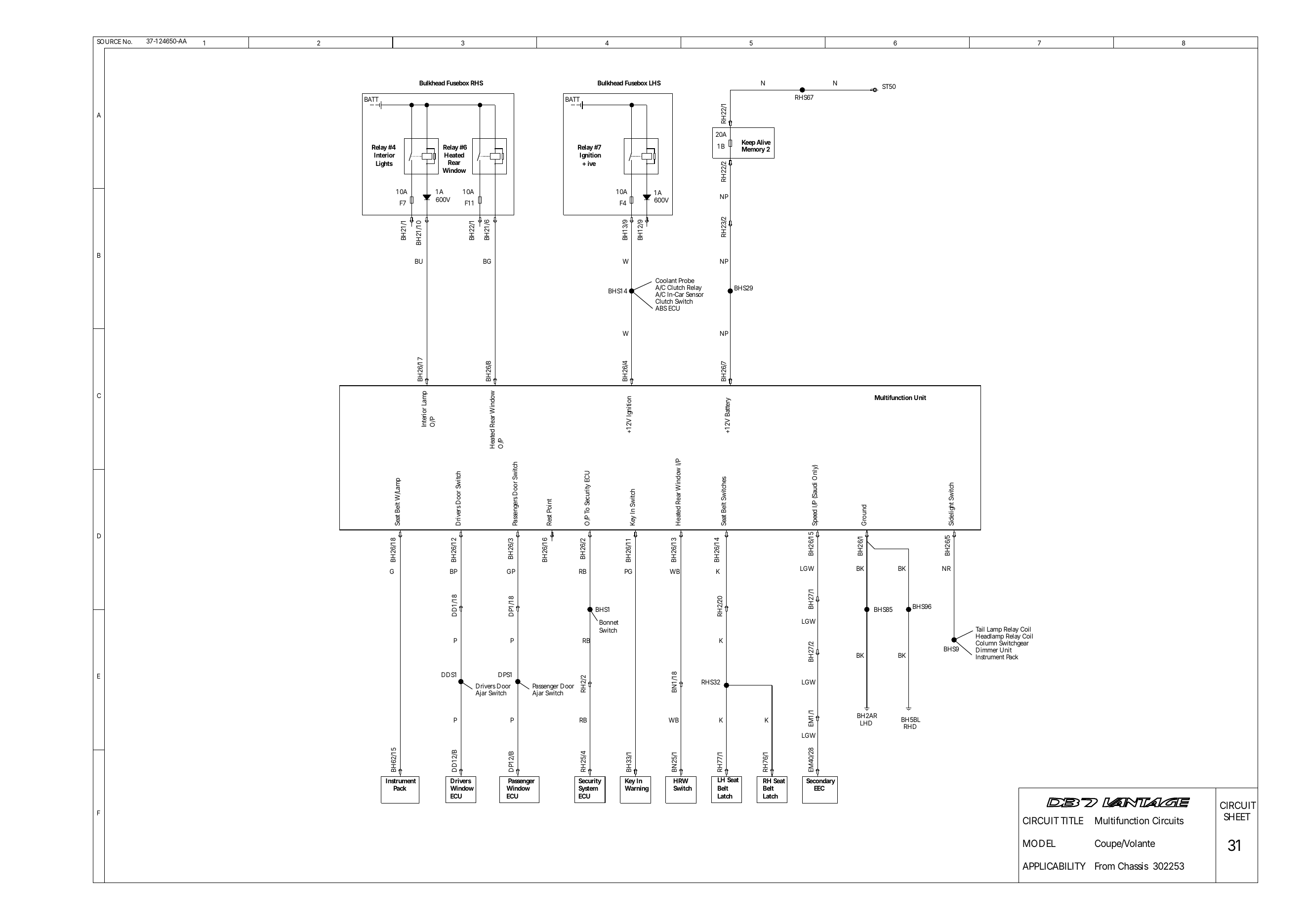
Which cars: this is the 2002 model year set (from chassis 302253), the one included in the Workshop Manual. Most circuits are the same on earlier cars, but there were significant wiring changes at 302253, so check connector and pin numbers against the car. Current flows top to bottom on each sheet; splices are labelled by harness (e.g. BHS13 = bulkhead harness splice 13).
B blackN brownR redO orangeY yellowG greenLG light greenU blueP purpleK pinkS slateW whitetwo letters = main colour, then tracer
V12 Vantage component locations
Component locations
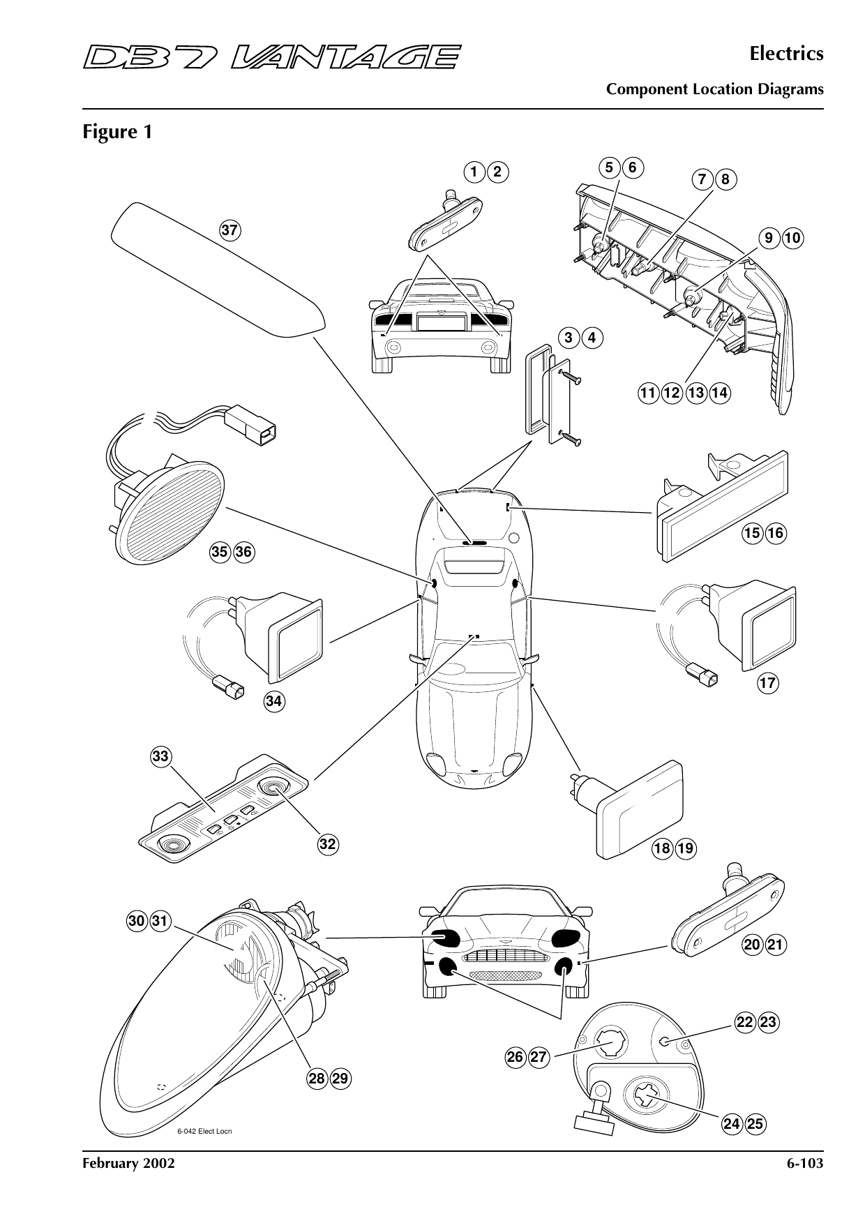
Figure 1: Lamps
Shows: Boot Lamp - LH, Boot Lamp - RH, Interior Lamp - Front, Interior Lamp - LH Rear, Interior Lamp - RH Rear, Lamp - Dip Beam LH, Lamp - Dip Beam RH …
Component locations
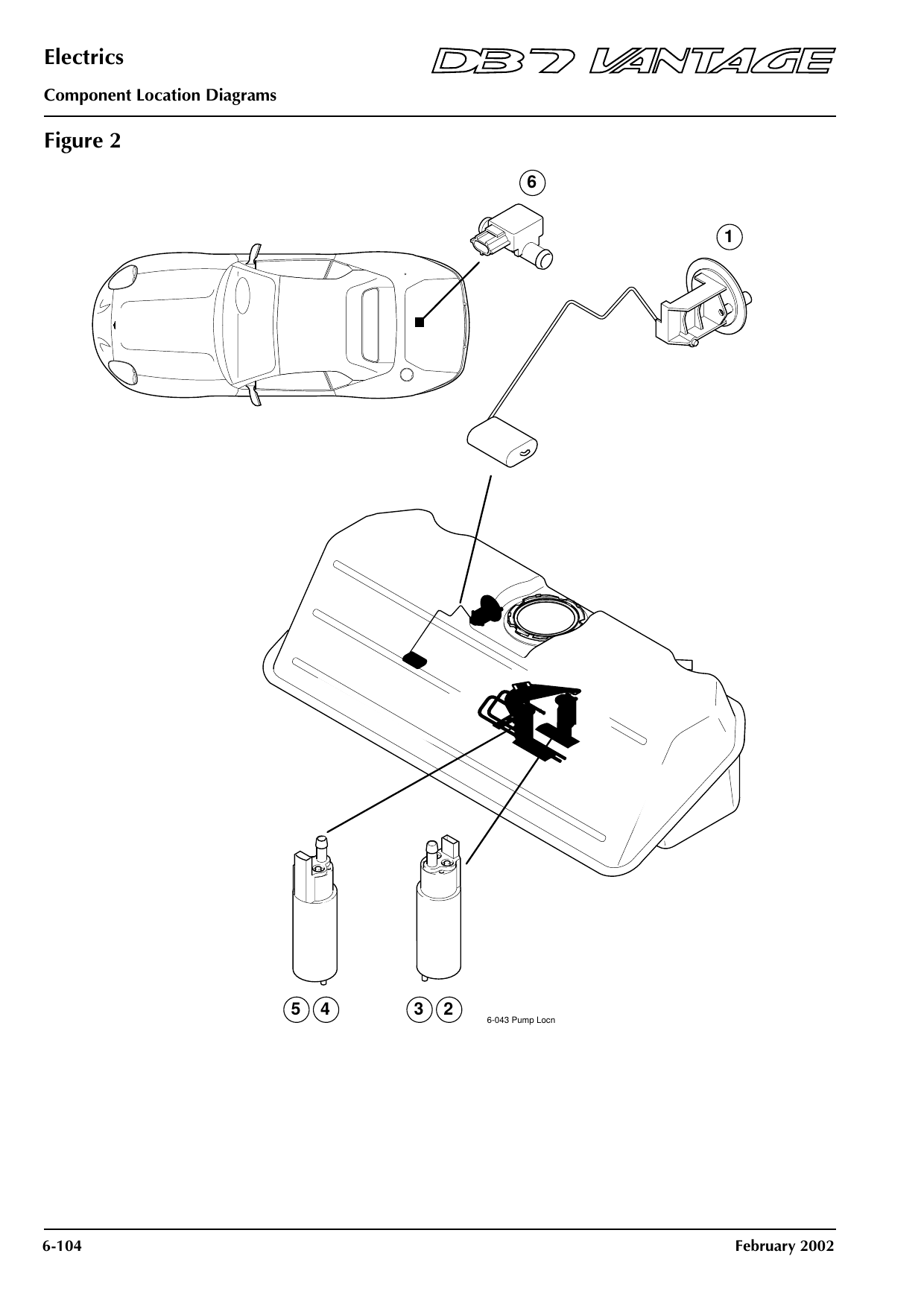
Figure 2: Fuel tank and pumps
Shows: Fuel Pump 1, Fuel Pump 2, Sensor - Fuel Level, Sensor - Fuel Tank Pressure
Component locations
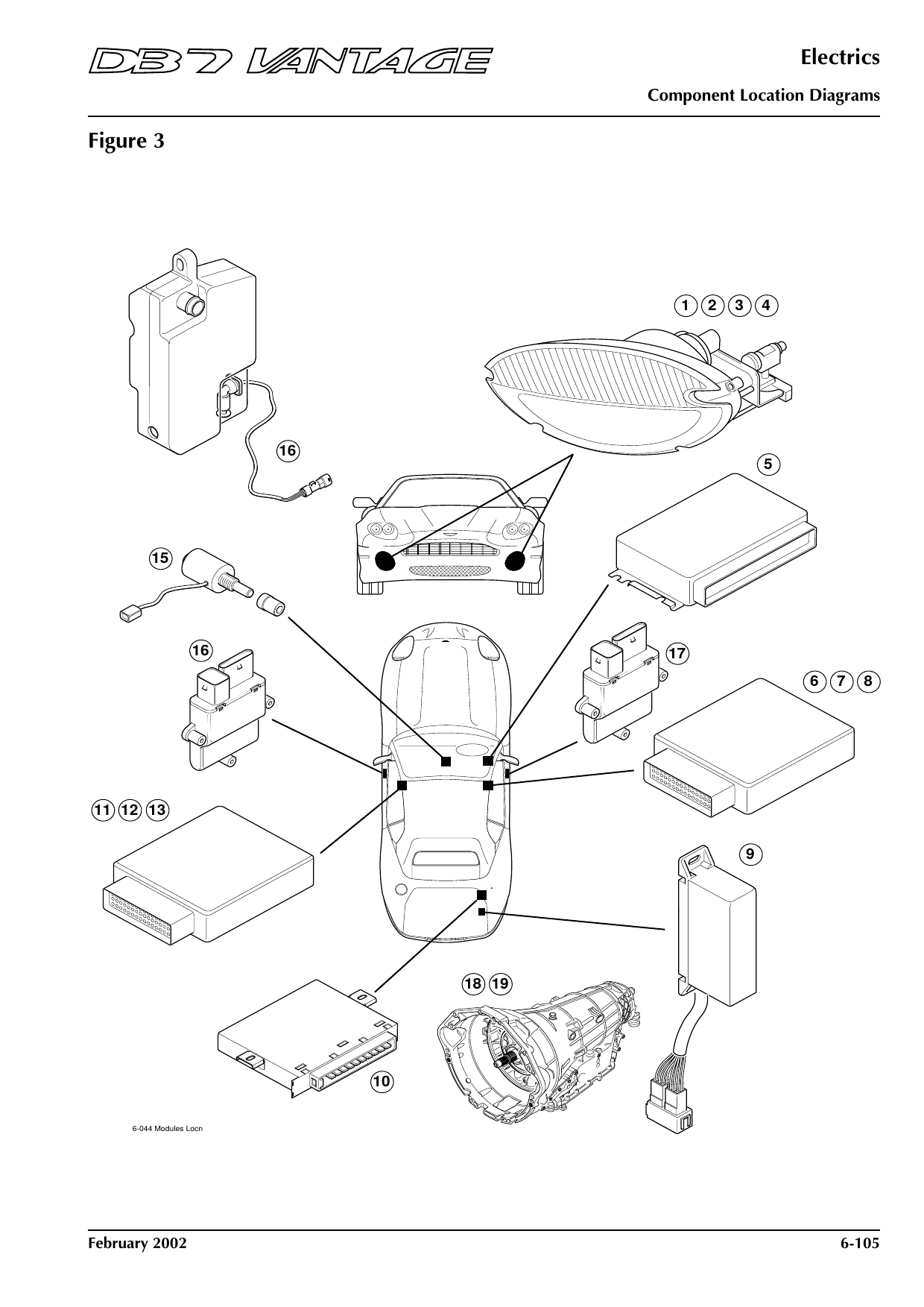
Figure 3: Control modules
Shows: Door Window Controller (Convertible) - Driver’s Door, Door Window Controller (Convertible) - Passenger’s Door, Door Window Controller (Coupe) - Driver’s Door, Door Window Controller (Coupe) - Passenger’s Door, Flasher Unit - Direction Indicators, Flasher Unit - Hazard Lamps, Gearshift Interlock Solenoid …
Component locations
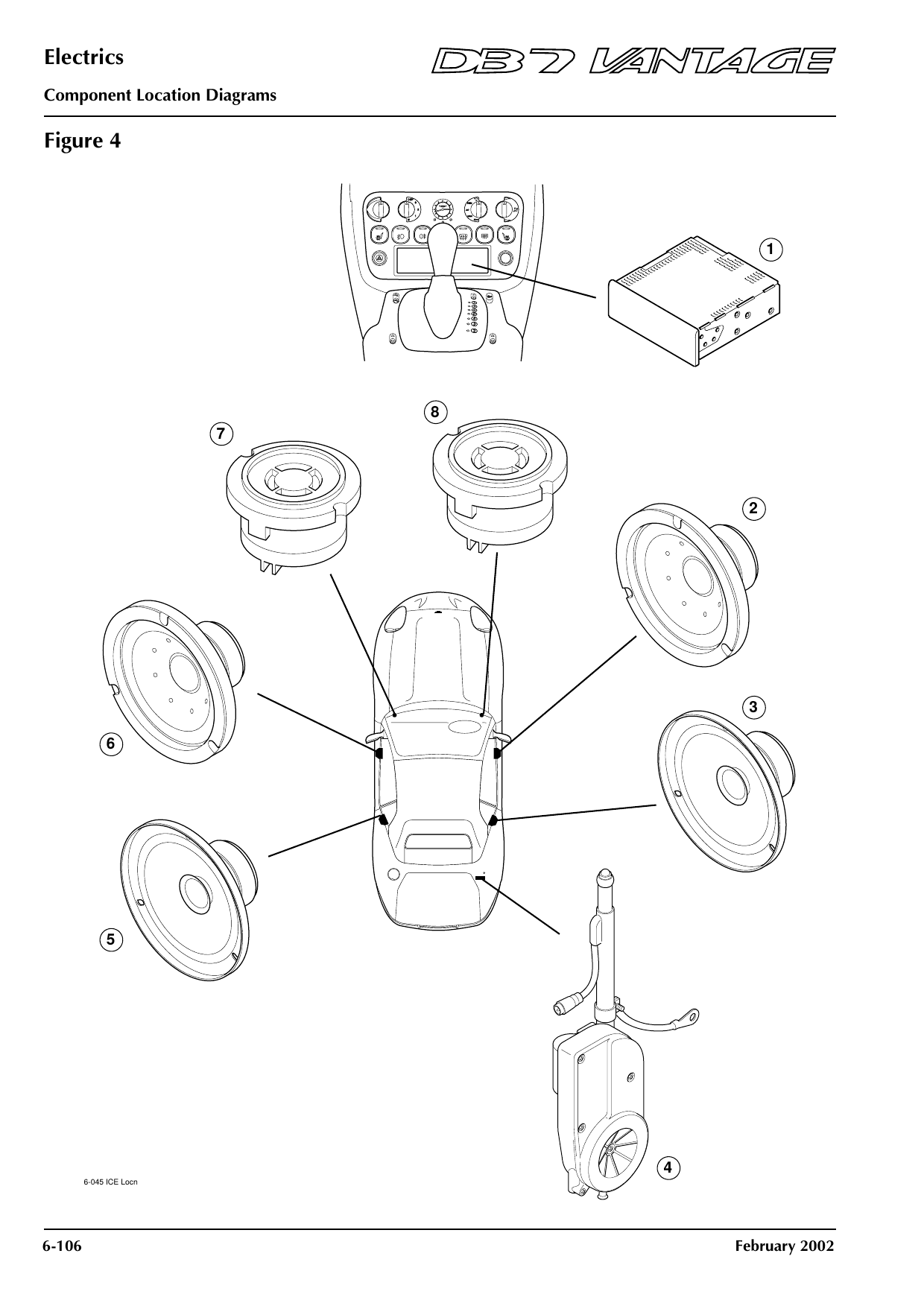
Figure 4: In-car entertainment
Shows: Aerial - Radio, Speaker - Driver’s Side Rear, Speaker - Drivers Door, Speaker - Drivers Side Bulkhead Tweeter, Speaker - Passenger’s Door, Speaker - Passenger’s Side Bulkhead Tweeter, Speaker - Rear
Component locations
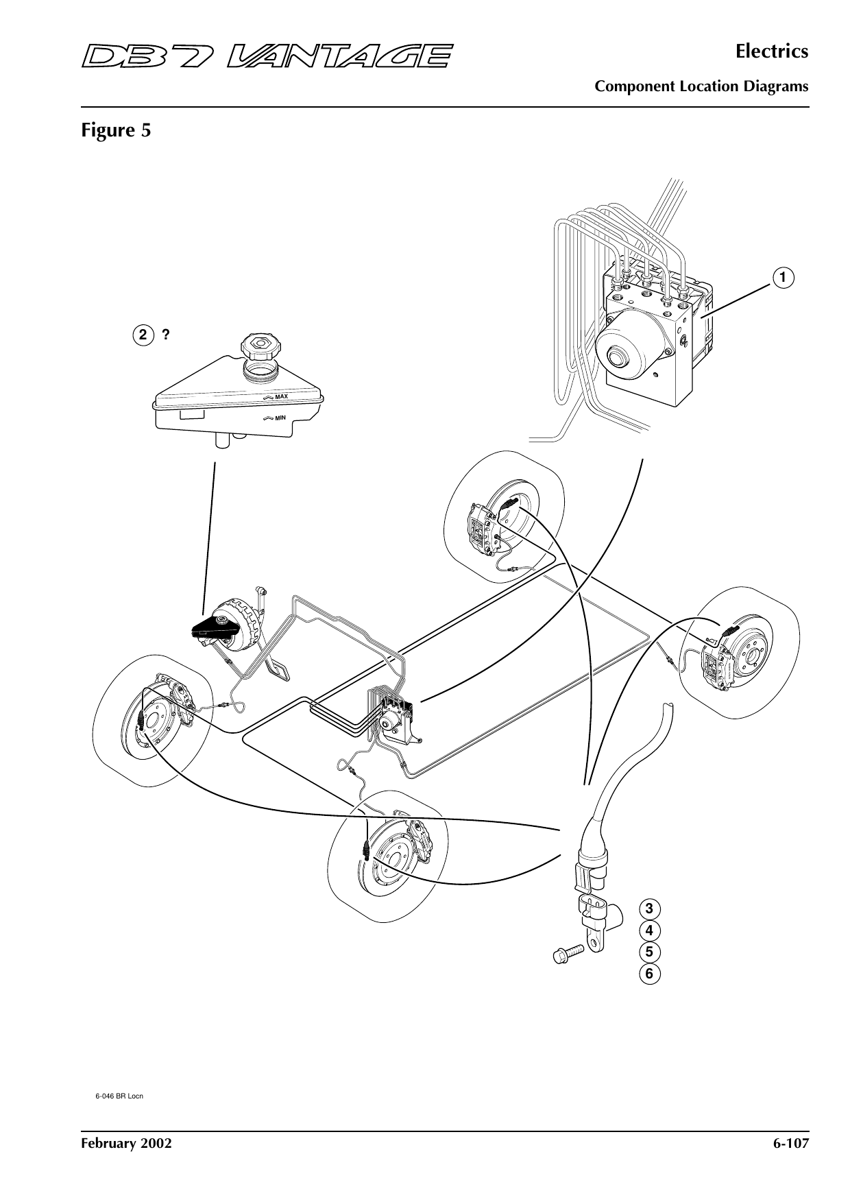
Figure 5: Brakes and ABS
Shows: ABS Control Unit, ABS Fluid Level Sensor, Sensor - ABS Wheel Speed - Left Front, Sensor - ABS Wheel Speed - Left Rear, Sensor - ABS Wheel Speed - Right Front, Sensor - ABS Wheel Speed - Right Rear
Component locations
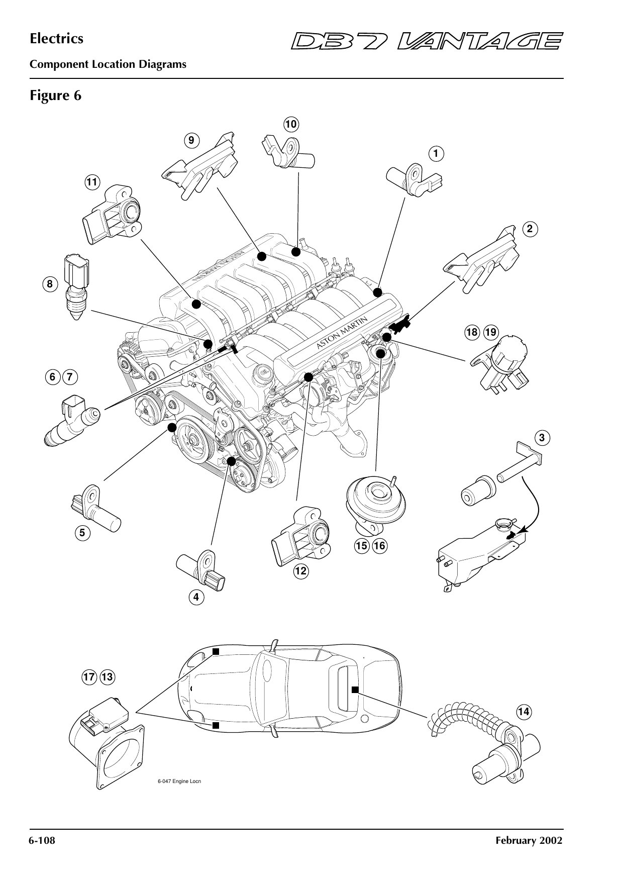
Figure 6: Engine
Shows: EGR Vacuum Regulator (Left Hand), EGR Vacuum Regulator (Right Hand), Fuel Injectors 1-6 (Right Hand Bank), Fuel Injectors 7-12 (Left Hand Bank), Sensor - Crankshaft Position (Left Hand Bank), Sensor - Crankshaft Position (Right Hand Bank), Sensor - Cylinder ID (Camshaft Sensor Left Hand Bank) …
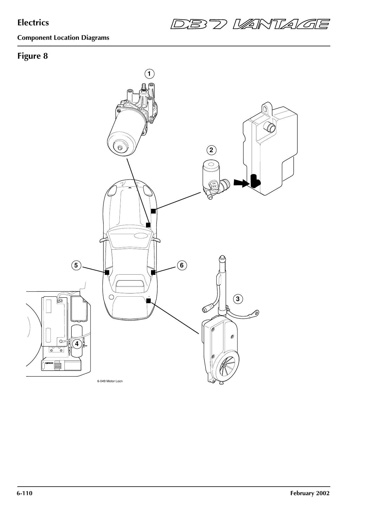
Component locations
Figure 8: Motors
Shows: Motor - Hood Pump (Convertible), Motor - Left Quarter Light Lift (Convertible), Motor - Radio Aerial, Motor - Right Quarter Light Lift (Convertible), Screenwash Pump, Wiper Motor
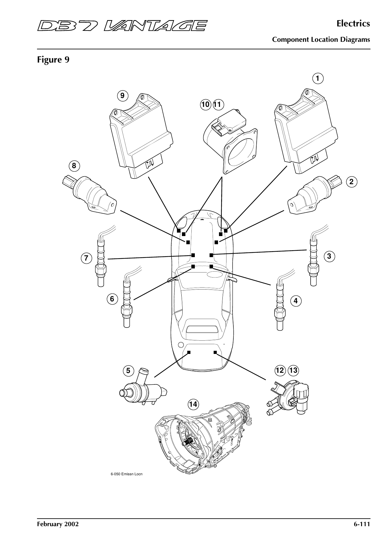
Component locations
Figure 9: Emissions and engine sensors
Shows: Cannister Vent Valve (Left Hand), Catalyst Monitor Sensor (Rear Left), Catalyst Monitor Sensor (Rear Right), Heated Oxygen Sensor (Front Left), Heated Oxygen Sensor (Front Right), Idle Air Control Valve (Left Hand), Idle Air Control Valve (Right Hand) …
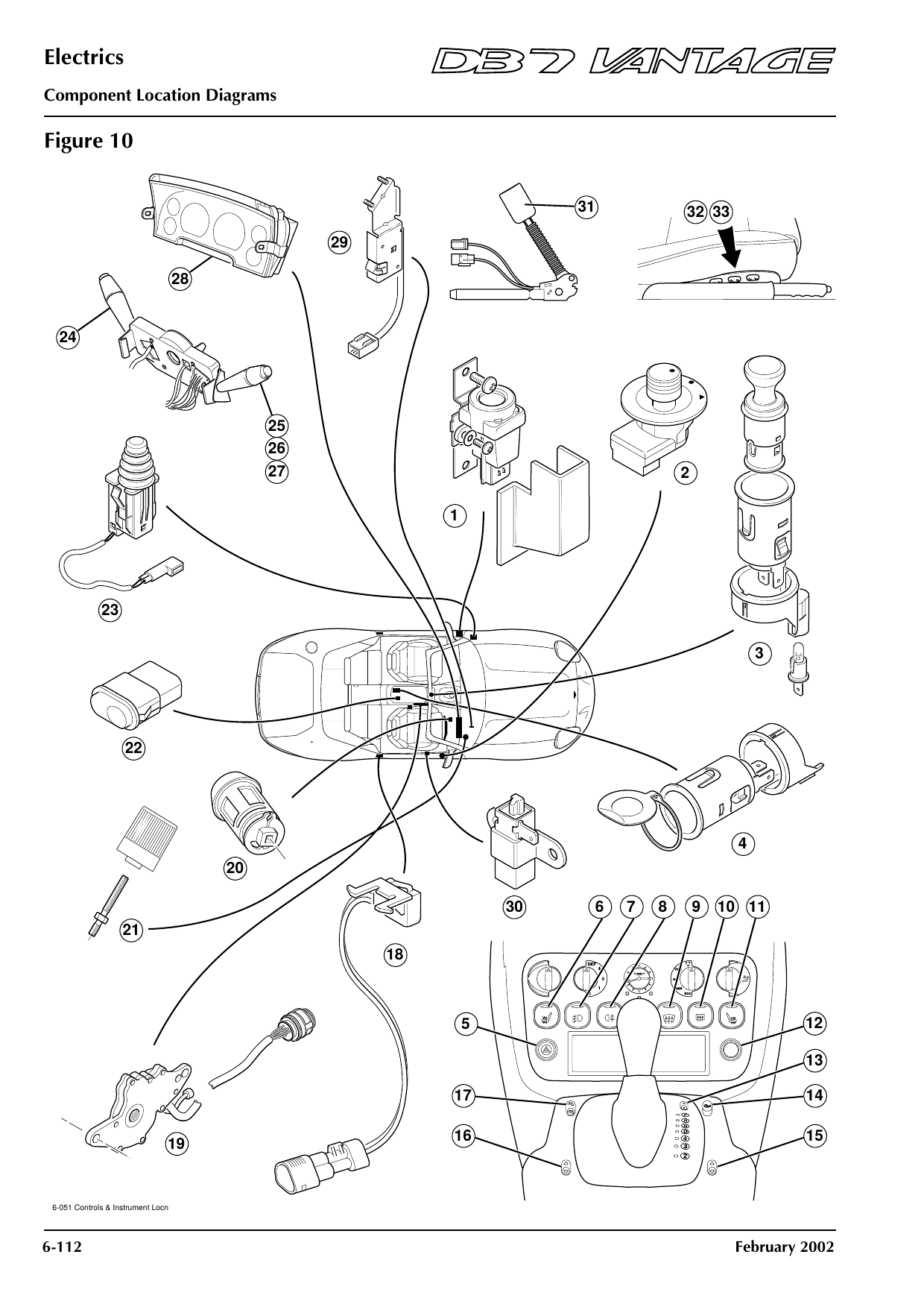
Component locations
Figure 10: Switches and controls
Shows: Cigar Lighter, Door Mirror Switch - Driver’s, Instrument Pack, Seat Heater Switch - Driver’s, Seat Heater Switch - Passenger’s, Seat Switch Pack - Driver’s, Seat Switch Pack - Passenger’s …
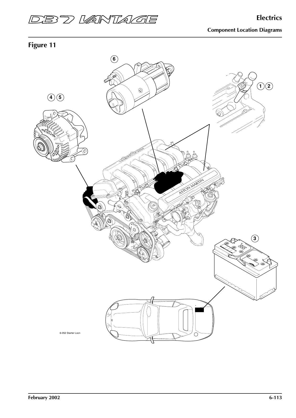
Component locations
Figure 11: Starting and charging
Shows: Alternator, Battery, Ignition Coils 1-6 (Right Hand Bank), Ignition Coils 7-12 (Left Hand Bank), Starter Motor
Component locations
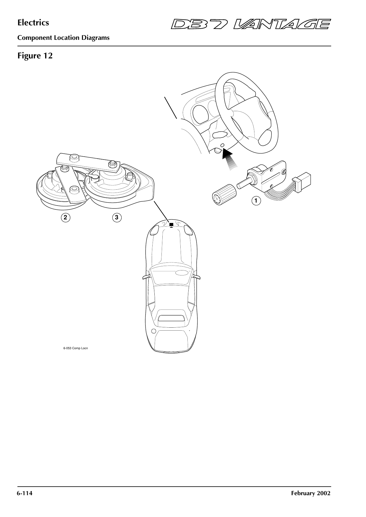
Figure 12: Underbonnet components
Shows: Horn - Left Hand, Horn - Right Hand, Illumination Control Pot
Component locations
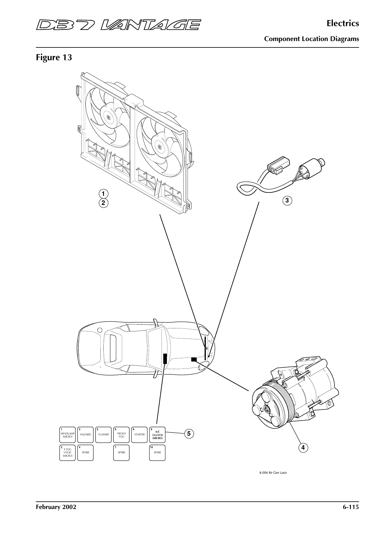
Figure 13: Air conditioning and cooling
Shows: Air Conditioning - Clutch Relay, Air Conditioning - Compressor Clutch, Air Conditioning - Trinary Switch, Cooling Fan - Radiator Left Side, Cooling Fan - Radiator Right Side
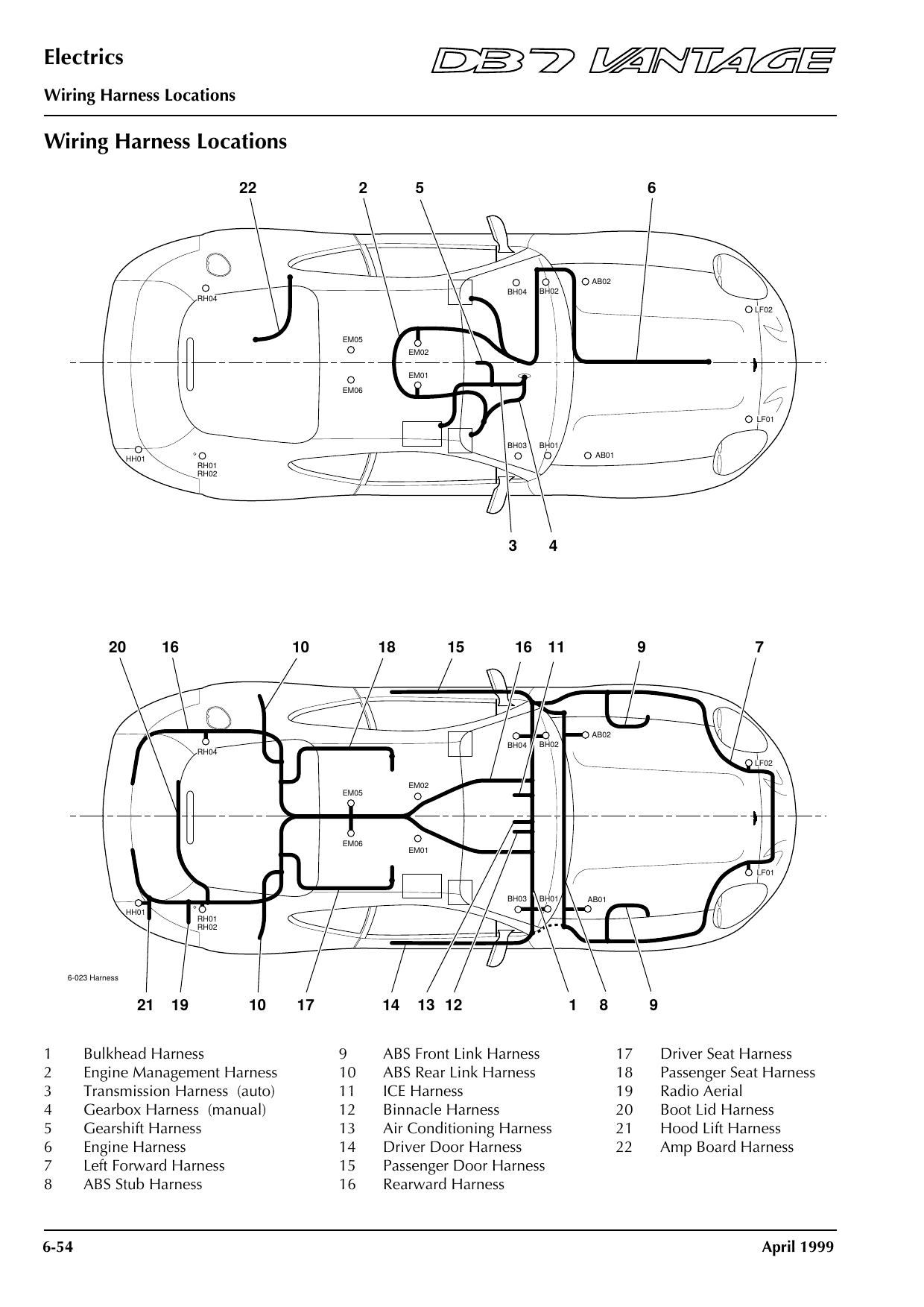
Not shown: security/alarm, immobiliser (PATS), tracker and airbag circuits and their component locations are left out, as on the rest of the site. For those systems, see an Aston Martin dealer or a qualified specialist. Always disconnect the battery before working on wiring, and treat these drawings as a guide — harnesses were changed during production.
Ask the Manual about a fault →