Where every fuse box is, and what every fuse protects — number, amp rating and circuit — taken from the factory documents: the i6 Owner’s Guide (Issue 3, 1997) and the V12 Vantage Workshop Manual (April 1999 and April 2000 issues). Pick your car below, then search for a circuit or tap a marker on the car.
i6 — fuse box locations
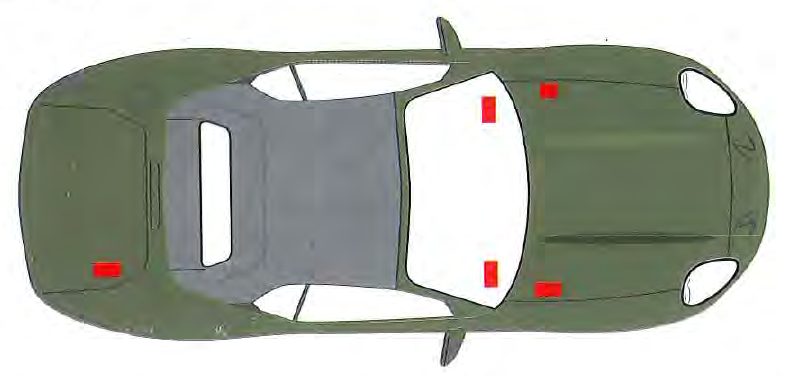
Five fuse boxes. Viewed from above, front to the right. Showing a right-hand-drive car.Showing a left-hand-drive car.
Factory diagram — i6 Owner’s Guide, p 1-126 (fuse boxes marked in red, front to the right) · tap to enlarge
V12 Vantage — fuse & relay locations
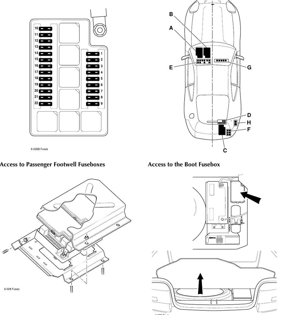
Three fuse/relay boxes (A, B, C) and relay brackets D–H. Viewed from above, front to the right. Showing a right-hand-drive car.Showing a left-hand-drive car. Bulkhead brackets E and G are reached by removing the driver’s or passenger’s underscuttle.
Factory illustration — V12 Vantage Workshop Manual, p 6-48: fuse layout, locations (RHD shown), footwell and boot access · tap to enlarge
Chart colours: 5A7.5A10A15A20A25A30A40A — the usual blade-fuse colour for each rating. Always go by the rating printed on the fuse.
i6 fuse charts
LF
Left Forward Fuse Box
RHD
Where: Engine bay, on the left inner wing.
No.
Rating
Circuit
1
5A
Dim dip / daytime running lights
2
15A
Front fog lights
3
20A
Side lights
4
5A
Headlamps
5
10A
LH main beam
6
10A
RH main beam
7
5A
LH sidelights
8
5A
RH sidelights
9
7.5A
LH dipped beam
10
7.5A
RH dipped beam
11
5A
Fused auxiliary feed
12
20A
Air pump
13
15A
Horn
14
10A
Cruise control
15
5A
Heated washer jets
16
5A
Main beam flash
17
10A
Alarm sounder
LF
Left Forward Fuse Box
LHD
Where: Engine bay, on the left inner wing.
No.
Rating
Circuit
1
5A
Dim dip / daytime running lights
2
15A
Front fog lights
3
30A
Side lamps
4
5A
Head lamps
5
10A
LH main beam
6
10A
RH main beam
7
5A
LH sidelights
8
5A
RH sidelights
9
7.5A
LH dipped beam
10
7.5A
RH dipped beam
11
5A
Fused auxiliary feed
12
20A
Air pump
13
15A
Horn
14
10A
Cruise control
15
5A
Heated washer jets
16
5A
Main beam flash
17
10A
Alarm sounder
RF
Right Forward Fuse Box
RHD & LHD
Where: Engine bay, on the right inner wing.
Houses the two 30A cooling fan maxi fuses alongside the air-conditioning and fan relays (Workshop Manual Vol 2, Relay Location Index 97 MY). The Owner’s Guide gives no separate fuse list for this box.
D
Driver’s Side Fuse Box
RHD
Where: Behind the pull-down panel beneath the facia, driver’s (right) side.
No.
Rating
Circuit
1
—
Not used
2
15A
Direction indicators
3
20A
RH air conditioning fan
4
5A
Air conditioning relay
5
10A
OBD II battery
6
5A
Interior lights
7
5A
Electric window lift / mirrors / hood control
8
10A
Screen wash pump
9
10A
Drivers seat heater
10
20A
Ignition / alternator
11
5A
Transmission control module ignition feed
12
20A
Drivers seat control power
13
5A
Battery / GSI / clock
14
5A
Instrument pack
15
5A
Air conditioning control
16
5A
Gear shift illumination (GSI)
17
7.5A
Rear fog lights
18
7.5A
Control switch - internal location lamps
19
15A
Hazard warning
20
20A
Cigar lighter
21
5A
Transmission control module
22
30A
Heated rear screen / heated door mirrors
D
Driver’s Side Fuse Box
LHD
Where: Behind the pull-down panel beneath the facia, driver’s (left) side.
No.
Rating
Circuit
1
—
Not used
2
10A
OBD II battery
3
20A
LH air conditioning fan
4
10A
Radio power
5
5A
Radio ignition feed
6
5A
ABS ECU
7
5A
Electric window lift / mirrors / hood
8
10A
Screen wash pump
9
10A
Drivers seat heater
10
5A
Radio telephone auxiliary
11
15A
Direction indicators
12
20A
Drivers seat control power
13
30A
ABS control unit valves
14
20A
Accessory battery
15
5A
Accessory auxiliary
16
5A
Ignition feed instrument pack
17
10A
Rear fog lights
18
10A
Locate illumination
19
15A
Hazard warning
20
20A
Ignition coil / alternator
21
20A
Left forward ignition feed
22
30A
Heated rear screen / heated door mirrors
P
Passenger Side Fuse Box
RHD
Where: Behind the pull-down panel beneath the facia, passenger (left) side.
No.
Rating
Circuit
1
—
Not used
2
15A
Central door locking / multi-function
3
20A
LH air conditioning fan
4
10A
Radio power
5
5A
Radio ignition feed
6
7.5A
Oxygen sensor heaters
7
5A
Gearbox ignition
8
25A
Windscreen wipers
9
10A
Passenger seat heater
10
5A
Radio telephone auxiliary
11
30A
ABS valves
12
20A
Passenger seat control power
13
30A
Engine management
14
5A
Accessory auxiliaries
15
10A
Air bag ignition feed / seat belt pre-tensioner
16
10A
Airbag battery feed
17
5A
ABS control unit
18
15A
Accessory battery
19
20A
Boot ignition feed
20
5A
Inst. pack memory / engine management memory
21
20A
Left forward ignition feed
22
30A
ABS pump
Maxi
40A
Heated front screen
P
Passenger Side Fuse Box
LHD
Where: Behind the pull-down panel beneath the facia, passenger (right) side.
No.
Rating
Circuit
1
—
Not used
2
10A
Central door locking / multi-function
3
20A
RH air conditioning fan
4
10A
Air conditioning relay
5
5A
Interior lights
6
30A
Engine management
7
20A
Boot ignition feed
8
25A
Windscreen wipers
9
10A
Passenger seat heater
10
5A
Gearbox ignition supply
11
30A
Gear shift indicator / clock
12
20A
Passenger seat control power
13
5A
Gearbox ignition supply
14
5A
Gear shift indicator, ignition supply
15
5A
Air conditioning control
16
10A
Cigar lighter
17
10A
Airbag ignition supply / seat belt pre-tensioner
18
15A
Airbag battery
19
7.5A
Oxygen sensor heaters
20
5A
Instrument pack battery / engine ECU memory
21
5A
Gearbox control unit memory
22
30A
ABS pump
Maxi
40A
Heated front screen
R
Rear Fuse Box
RHD & LHD
Where: In the boot, close to the battery.
No.
Rating
Circuit
1
20A
Fuel pump 1
2
15A
Stop lamp supply
3
5A
Stop lamp relay
4
10A
Aerial / boot lamps
5
—
Not used
6
5A
LH tail lamp / LH number plate lamp
7
5A
RH tail lamp / RH number plate lamp
8
5A
Security system ignition feed
9
20A
Security system battery
10
5A
Reverse lamp relay
11
5A
Reverse lamp supply
12
20A
Fuel pump 2
Source: i6 Owner's Guide, Issue 3 (Feb 1997), pages 1-126 to 1-132. Spare bayonet fuses are in each fuse box. A spare 40A maxi fuse (heated front screen) and a fuse extractor key are in the bulb/fuse kit in the spare wheel insert under the boot floor covering. Fuse arrangements also differ between market variants — if a fuse doesn’t match the circuit on your car, check the label inside the fuse box cover.
V12 Vantage fuse charts
A
A — Footwell Fusebox, Left Hand
to chassis 300555
Where: Passenger footwell, beneath a plate — left footwell on this right-hand-drive carright footwell on this left-hand-drive car.
Box face, fuses and relays as laid out in the factory illustration. Tap a fuse to find it in the list.
No.
Rating
Circuit
1
15A
Accessory terminal
2
10A
Transmission control module
3
5A
Headlamp relay, instrument pack, dimmer unit
4
10A
Multi function unit, A/C in-car sensor, ABS control unit
5
5A
Traction control switch, alternator regulator, heated front screen control
6
10A
Rear fog switch, RH dip beam
7
30A
Starter relay
8
10A
LH dip beam
9
20A
LHS seat heater relay, LHS seat module
10
40A
Heated front screen controller
11
10A
RH horn
12
30A
LH rad cooling fan
13
10A
LH horn
14
30A
RH rad cooling fan
15
30A
Primary PCM RHS
16
10A
MFU, central locking, A/C control panel, alarm sounder
17
30A
Secondary PCM LHS
18
5A
Interior map lights, instrument pack, RH rad module
The April 2000 manual prints 30A for the main beam positions 15 and 17.
B
B — Footwell Fusebox, Right Hand
all chassis
Where: Passenger footwell, beneath a plate — left footwell on this right-hand-drive carright footwell on this left-hand-drive car.
Box face, fuses and relays as laid out in the factory illustration. Tap a fuse to find it in the list.
No.
Rating
Circuit
1
5A
Unused
2
20A
Cigar lighter
3
10A
Diagnostic body & powertrain, ICE, A/C unit, aux power hood
4
5A
Seat switches and heaters
5
10A
Indicator flasher
6
10A
Ignition coils 1-6
7
10A
Interior lamp cluster
8
10A
Ignition coils 7-12
9
20A
RHS seat heater relay, RHS seat module
10
10A
Dimmer, PATS, ICE
11
10A
Heated rear window telltale, door mirrors
12
5A
Diagnostic socket, alternator
13
25A
Heated rear window
14
10A
Hazard flasher unit
15
20A
Wiper logic module and wiper stalk
16
30A
ABS control unit
17
20A
Wiper motor, logic module and wiper stalk
18
30A
ABS control unit
19
10A
A/C LH blower motor
20
5A
Gearshift interlock module, traction control switch, interior lamp
21
10A
A/C RH blower motor
22
10A
PCM and TCM keep alive power
C
C — Boot Fusebox
to chassis 300555
Where: In the boot, close to the battery.
Box face, fuses and relays as laid out in the factory illustration. Tap a fuse to find it in the list.
No.
Rating
Circuit
1
10A
Reverse light relay
2
20A
Security ECU, glass break sensor
3
5A
+12V ignition, fusebox sense
4
5A
Trunk logic relay, hood, security system control module
5
30A
Accessory terminal
6
5A
RH fog lamp, RHS EEC, LHS EEC, brake switch input
7
20A
Fuel pump 2, LHS EEC
8
10A
HM stop light, LH stop light
9
10A
Boot lamps, radio aerial motor
10
10A
Accessory socket
11
20A
LH quarter light up/down relay
12
20A
RH quarter light up/down relay
13
10A
Airbag ECU
14
30A
Hood up/down relay
15
20A
Fuel pump 1, RHS EEC
16
10A
Rear fog light relay
17
10A
Manual gearbox cooling pump
18
10A
Accessory terminal
19
10A
RH tail, side, side marker and number plate lamps
20
20A
Premium ICE amplifier
21
10A
LH tail, side, side marker and number plate lamps
22
20A
Premium ICE
C
C — Boot Fusebox
from chassis 300556
Where: In the boot, close to the battery. The 30A Premium ICE in-line fuse is in the loom at the fusebox +ve terminal.
Box face, fuses and relays as laid out in the factory illustration. Tap a fuse to find it in the list.
No.
Rating
Circuit
1
10A
Reverse light relay
2
20A
Security ECU, glass break sensor
3
5A
+12V ignition, fusebox sense
4
5A
Trunk logic relay, hood, security system control module
5
5A
EEC relay ignition
6
5A
RH fog lamp, RHS EEC, LHS EEC, brake switch input
7
20A
Fuel pump 2, LHS EEC
8
10A
HM stop light, LH stop light
9
10A
Boot lamps, radio aerial motor
10
10A
Accessory socket
11
20A
LH quarter light up/down relay
12
20A
RH quarter light up/down relay
13
10A
Airbag ECU
14
30A
Hood up/down relay
15
20A
Fuel pump 1, RHS EEC
16
10A
Rear fog light relay
17
10A
Manual gearbox cooling pump
18
10A
EECV power
19
10A
RH tail, side, side marker and number plate lamps
20
20A
EECV power
21
10A
LH tail, side, side marker and number plate lamps
22
20A
Not used
In-line
30A
Premium in-car entertainment (in the loom at the boot fusebox +ve terminal)
Source: V12 Vantage Workshop Manual Vol 3: pages 6-48 to 6-53 (April 1999) and 6-89 to 6-93 (April 2000, "From Chassis 300556"). Spare bayonet fuses are in each fuse box. A spare 40A maxi fuse (heated front screen) and a fuse extractor are in the bulb/fuse kit in the spare wheel insert under the boot floor covering. Not sure of your chassis number? It’s on the VIN plate; the manual’s changes start at chassis 300556 (2000 model year).
V12 Vantage relay brackets
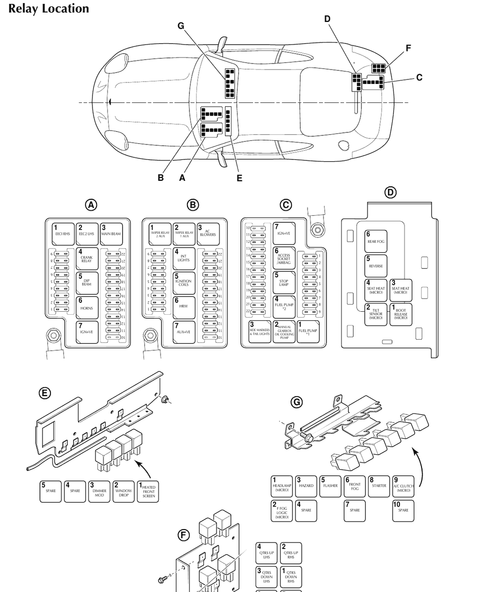
Factory relay locations to chassis 300555 — Workshop Manual p 6-52 (April 1999) · tap to enlarge
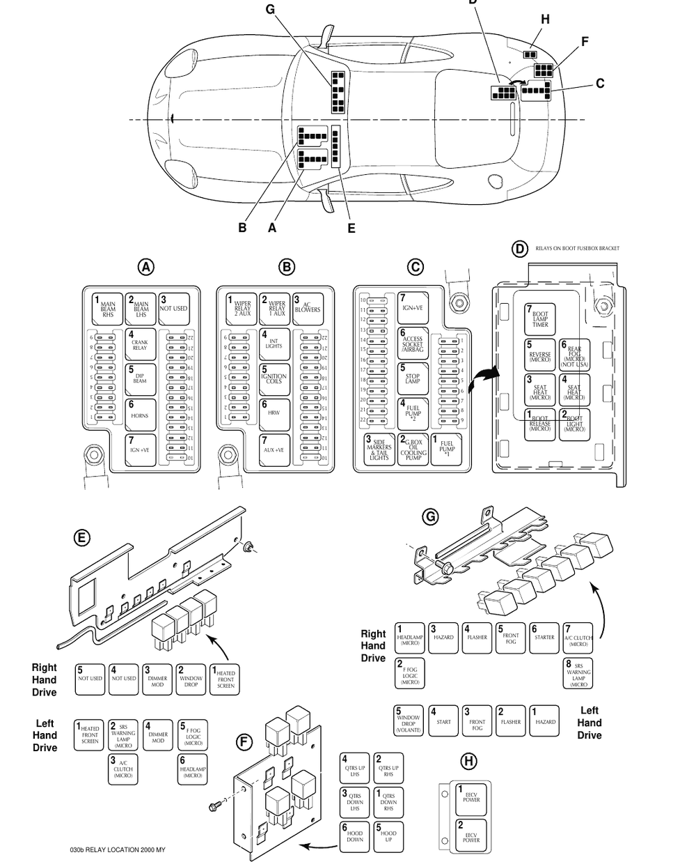
Factory relay locations from chassis 300556 — Workshop Manual p 6-92 (April 2000) · tap to enlarge
D — Boot fusebox bracket
to 300555
1 Boot release (micro)
2 Tilt sensor (micro)
3 Seat heater (micro)
4 Seat heater (micro)
5 Reverse light
6 Rear fog light
D — Boot fusebox bracket (beneath box C)
from 300556
1 Boot release (micro)
2 Boot light (micro)
3 Seat heater (micro)
4 Seat heater (micro)
5 Reverse light (micro)
6 Rear fog (micro, not Federal cars)
7 Boot lamp timer
E — Bulkhead bracket behind the fascia
RHD, to 300555
1 Heated front windscreen timer
2 Window drop
3 Dimmer module
4 Not used
5 Not used
G — Bulkhead bracket behind the fascia
RHD, to 300555
1 Headlamp (micro)
2 Front fog logic (micro)
3 Hazard
4 Not used
5 Flasher
6 Front fog
7 Not used
8 Starter
9 A/C clutch (micro)
10 Not used
E — Bulkhead bracket behind the fascia
LHD, to 300555
1 Hazard unit
2 Flasher unit
3 Front fog
4 Starter
5 Window drop (Volante only)
G — Bulkhead bracket behind the fascia
LHD, to 300555
1 Heated front windscreen timer
2 Not used
3 A/C clutch (micro)
4 Not used
5 Dimmer relay control
6 Headlamp (micro)
7 Front fog logic (micro)
8 Not used
9 Not used
10 Not used
E — Left bulkhead bracket
RHD, from 300556
1 Heated front windscreen timer
2 Window drop (Volante only)
3 Dimmer module
4 Not used
5 Not used
G — Right bulkhead bracket
RHD, from 300556
1 Headlamp (micro)
2 Front fog logic (micro)
3 Hazard
4 Flasher
5 Front fog
6 Starter
7 A/C clutch (micro)
8 Airbag warning lamp
E — Left bulkhead bracket
LHD, from 300556
1 Heated front windscreen timer
2 Airbag warning lamp (micro)
3 A/C clutch (micro)
4 Dimmer relay control
5 Front fog logic (micro)
6 Headlamp (micro)
G — Right bulkhead bracket
LHD, from 300556
1 Hazard unit
2 Flasher unit
3 Front fog
4 Starter
5 Window drop (Volante only)
F — Hood harness bracket (Volante)
all chassis
1 RH quarter light down (micro)
2 RH quarter light up (micro)
3 LH quarter light down (micro)
4 LH quarter light up (micro)
5 Hood up
6 Hood down
H — Engine management relay bracket
from 300556
1 EECV power
2 EECV power
No fuse matches that search for this car. Try another word, or ask the manual.
Before you change a fuse: switch off the ignition and the circuit. Never fit a fuse rated higher than the chart shows, and never repair a blown fuse — both are a fire risk. If the same fuse blows again, there is a short or a failing component on that circuit: find the cause before fitting another.
Common questions
Where are the fuse boxes on an Aston Martin DB7 i6?
The i6 has five fuse boxes: left forward and right forward on the inner wings in the engine bay, driver side and passenger side behind pull-down panels beneath the facia, and a rear fuse box in the boot close to the battery. The driver and passenger box contents differ between right- and left-hand drive cars.
Where are the fuse boxes on a DB7 V12 Vantage?
The V12 Vantage has three fuse/relay boxes. Boxes A and B are beneath a plate in the passenger footwell (left footwell on right-hand drive cars, right footwell on left-hand drive cars). Box C is in the boot, close to the battery. All three share the same 22-position fuse layout and each holds seven relays.
Which fuse is the fuel pump on a DB7?
i6: rear fuse box (boot) fuse 1, 20A (fuel pump 1) and fuse 12, 20A (fuel pump 2). V12 Vantage: boot fusebox C fuse 15, 20A (fuel pump 1, RHS EEC) and fuse 7, 20A (fuel pump 2, LHS EEC); the fuel pump relays are positions 1 and 4 in box C.
Where are the spare fuses?
Spare bayonet fuses are located in each fuse box. A spare 40A maxi fuse for the heated front screen and a fuse extractor are in the bulb and fuse kit, stored in the spare wheel insert under the boot floor covering.